@KevinHeem thanks for the tip! Mine is mounted in a socket and I checked it and it was fine. I usually am pretty good with DIP sockets because about 40 years ago I inserted thousands of memory chips into sockets (DIP-16) to upgrade the memory in PCs. Memory chips were expensive in those days, so you learned to be careful ")
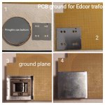
@Zen Mod Thanks for the test points. This helped a lot. I assume 1 is to see if the signal is coming in, 2 if the jfets are working, 3 if the edcor is providing the gain expected and 4 to see if the output stage is working.
I just finished testing the amp but left my notes in the shed, so the numbers are as close as I remember them.
I mounted the pcb back onto the heatsink and hooked up the amp to my bench psu (+/-24VDC). I connected a source with a 1kHz sine wave signal and measured about 154mV at the input (IN).
The measurements at points 1 and 2 were slightly below the input (without my notes I estimate 1%), but to all intents and purposes it showed that the input was coming in and the jfets were working as expected.
The surprise was the level at point 3, only 90 something mV. The heatsink was getting nice and warm, so I assumed the output stage was working. The measurement at 4 confirmed this, it was just about the same as at 3 (as expected because output stage is a no voltage gain follower).
DC at 4 was easily adjusted to 0mV.
The drop between points 2 and 3 to me pointed to a problem with the Edcor. I had checked before to make sure it was mounted correctly (it was), so assumed it was not working as intended. Luckily I had bought 4 of these when I bought the boards (many years ago), so I had a spare to try.
I replaced the Edcor but was running out of time because my helper could not stay any longer, so without any further measurements we quickly reassembled the amp, connected test speakers and source and switched it on. It is working perfectly! I was only able to listen for a few minutes, but both channels sounded fine on the crappy test speakers I have in my shed.
Next week, when my helper is back, we can put it together properly. I also still need to wire the front panel leds and a few other things, so that will be the next job. When finished, we can let it cook and do final adjustments.
After that it will go in to my main system, where I can properly judge what it sounds like. It will take the place of my Aleph 3, powering mid/hi only of my Magnepan MG3As.
Thanks for your help with this. Much appreciated.
Next thing to work out is how to test what is wrong with the Edcor, and if it can be fixed. Time to read the datasheet!


I seem to remember reading about someone with an Edcor where one of the fine wires connecting the pins had gotten loose. Hopefully it's something simple like that to fix.
You remember correctly. It happened to me. Fortunately, I noticed one of the fine wires was loose before soldering the Edcor onto the board. It was an easy fix, but I couldn't have done it without using a magnifying lamp.
I had a look at the datasheet and will try continuity tests on pins 1-2-3 (IN+, CT and IN-) and 5-6-7 (OUT-, CT and OUT+). From the schematic I understand only 1, 3, 5 and 7 are connected to the circuit, so it will be interesting to see what my measurements show as I have trouble understanding how the edcor with a broken wire/unconnected pin can still produce sound, albeit at a lower level. Note though that I am thinking in terms of a normal transformer, not an autoformer. I'll have to look up how autoformers work first I think!
@albertNL
Good sleuthing.
Read posts 3507-3520.
One thing I have learned with transformers and particularly Edcor open frame models with those pesky tiny internal wires is that you have to test those transformers before you ever solder them in circuit. At least start with continuity testing. Don’t assume anything. Best to also test it in situ within the circuit with the Zobel filter installed prior to installing all the other parts of the M2X. Once it passes that test, i.e. 100mV, automagically gets converted to 500mV on the output (for a 1:5 stepup), at a reasonable test frequency that a DMM can measure, i.e. 300-500Hz then you are good. I use an oscilloscope and test at 1khz cause I am geeky. Sometimes I just do a Bode Plot test and test from 20Hz to 20khz which gives me the most assurance.
But that’s me. I don’t like trouble shooting my builds. I like trouble shooting the builds of my colleagues .
Once you do enough trouble shooting, you end up investing in an oscilloscope and never look back. Actually seeing that the sine wave stops at a specific section points to the troublesome part of the circuit as ZM has graciously shown you.
Best,
Anand.
Good sleuthing.
Read posts 3507-3520.
One thing I have learned with transformers and particularly Edcor open frame models with those pesky tiny internal wires is that you have to test those transformers before you ever solder them in circuit. At least start with continuity testing. Don’t assume anything. Best to also test it in situ within the circuit with the Zobel filter installed prior to installing all the other parts of the M2X. Once it passes that test, i.e. 100mV, automagically gets converted to 500mV on the output (for a 1:5 stepup), at a reasonable test frequency that a DMM can measure, i.e. 300-500Hz then you are good. I use an oscilloscope and test at 1khz cause I am geeky. Sometimes I just do a Bode Plot test and test from 20Hz to 20khz which gives me the most assurance.
But that’s me. I don’t like trouble shooting my builds. I like trouble shooting the builds of my colleagues
.Once you do enough trouble shooting, you end up investing in an oscilloscope and never look back. Actually seeing that the sine wave stops at a specific section points to the troublesome part of the circuit as ZM has graciously shown you.
Best,
Anand.
All of these we are usually using - be it Cinemag or Jensen or Edcor - they're made well and not overly fragile
Though, yes - good and clever and obligatory to check prior to soldering ....... just wanting to express my stance ( ZM, so Absolute Truth) that problems with said xformers are more than certainly result of brutal shipping, or negligence after unpacking them
Had both cases ...... first - what can I say - even Sherman tank couldn't live through abuse of that small box, second - well - ZM Omniclumsy
Quick update.
I measured the resistance of the windings of the edcor I took out with a dmm and get roughly 20r between pins 1-2. No connection from either 1 or 2 to pin 3, so the edcor is indeed faulty. Using a magnifying glass I can see the wire to pin 3 has broken off. I tried soldering it to the pin, bit is probably enamelled where it broke off, so unless I can get the enamel off at the end I cannot fix it.
While I was measuring, I thought I would have a look at the rest. I assumed that the resistance between pins 5&6 and 6&7 (OUT-&CT and CT&OUT+) would be the same, but is not: 107r vs 126r. I then tested my last spare and found the same values as on the other one (within 1%), so also not symmetrical.
I was also able to test the resistance between 1&2 and 2&3 on the spare, and they are also not symmetrical (19r8 and 23r5).
So, while the measurements were consistent between transformers, both are not symmetrical.
I then thought I would test some cinemag and jensen transformers I had bought for an f6 I never built.
Cinemags were more symmetrical on input side (1%), output side (1.5%) than jensen (2.4% and 3.5%).
I missed those because I read the entire thread when I made my notes, in September! Thanks for pointing it out!Read posts 3507-3520.
Would you believe I have an oscilloscope?One thing I have learned with transformers and particularly Edcor open frame models with those pesky tiny internal wires is that you have to test those transformers before you ever solder them in circuit. At least start with continuity testing. Don’t assume anything. Best to also test it in situ within the circuit with the Zobel filter installed prior to installing all the other parts of the M2X. Once it passes that test, i.e. 100mV, automagically gets converted to 500mV on the output (for a 1:5 stepup), at a reasonable test frequency that a DMM can measure, i.e. 300-500Hz then you are good. I use an oscilloscope and test at 1khz cause I am geeky. Sometimes I just do a Bode Plot test and test from 20Hz to 20khz which gives me the most assurance.
But that’s me. I don’t like trouble shooting my builds. I like trouble shooting the builds of my colleagues
Once you do enough trouble shooting, you end up investing in an oscilloscope and never look back. Actually seeing that the sine wave stops at a specific section points to the troublesome part of the circuit as ZM has graciously shown you.
I bought a Rigol DS1054 years ago and used it to debug oscillations on a diy Aleph P1.7 preamp. I never really mastered using it and tend to forget how useful it really is (if you know what you are doing that is
 ). They say a carpenter uses a hammer for everything, because it is the tool he is used to. My background is software, and debugging analog circuits is completely foreign. I recently restarted building amplifiers after a few years, and plan to learn to use the tools I have!
A friend gave me an Escort EGC-3235A that he had inherited and did not know what it was. It sat on my bench for a few years, not even plugged in. I looked up the specs recently and it is a 5MHz sweep function generator. See page 2 of https://dcfa.exa.unicen.edu.ar/wp-content/uploads/sites/18/2019/02/Function_generator.pdf
After reading your post, I searched for the manual and found one for the 3236a, which is similar. I have a lot of reading to do!
Hi all,
After the successful diy assembly of another PASS amplifier (the Aleph 30) and after enjoying it a LOT, I'm very motivated and planning to build the M2.
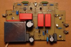
As the M2 has less components I'm thinking on using a 160x100 mm perforated pcb and making point to point soldering with copper wire (it's not the first time I do this, so I feel confident. In fact my TDA1541A nos DAC was made this way).
In any case I would like to share my first sketch of the pcb layout (it's hand-made, sorry for that) just to ensure it's correctness and maybe get some advice.
The overall dimensions of components should be substantially correct. The lines red highlighted with crayon shall be interpreted as galvanic bridges and the view is from above. Two upper corners are to be cut to place the mosfets.
I have a question regarding C2 (10uF). I have at home some MKP big caps and two of them can also be seen in the photo, so I would like to use one of them (the blue or the grey type). The blue is a big 10uF MKP high voltage X2 type and the grey is a Vishay 20uF (700V model 1848). I guess that the MKP shall be the best option in this position (signal path) and I also guess that 20 uF can work as well (or even marginally better regarding the low frequency cut-off) as the 10uF. I'm right?
(I would prefer the 20uF as it's the smaller of the two).
 .
.
Many thanks
After the successful diy assembly of another PASS amplifier (the Aleph 30) and after enjoying it a LOT, I'm very motivated and planning to build the M2.
As the M2 has less components I'm thinking on using a 160x100 mm perforated pcb and making point to point soldering with copper wire (it's not the first time I do this, so I feel confident. In fact my TDA1541A nos DAC was made this way).
In any case I would like to share my first sketch of the pcb layout (it's hand-made, sorry for that) just to ensure it's correctness and maybe get some advice.
The overall dimensions of components should be substantially correct. The lines red highlighted with crayon shall be interpreted as galvanic bridges and the view is from above. Two upper corners are to be cut to place the mosfets.
I have a question regarding C2 (10uF). I have at home some MKP big caps and two of them can also be seen in the photo, so I would like to use one of them (the blue or the grey type). The blue is a big 10uF MKP high voltage X2 type and the grey is a Vishay 20uF (700V model 1848). I guess that the MKP shall be the best option in this position (signal path) and I also guess that 20 uF can work as well (or even marginally better regarding the low frequency cut-off) as the 10uF. I'm right?
(I would prefer the 20uF as it's the smaller of the two).
Many thanks
Thanks
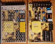
I'm making progress with my hand made pcb M2 (some pics below), hope to finish within January.
I decided to use switching power supply and bought two meanwell LRS-150-24 to make a series connection with center TAP to ground. First time I use switching PS.
But (there's always a but) despite 24V output Is galvanically isolated from the mains, I noticed (and confirmed) there are two ceramic capacitors between ground and negative output (marked in one pic below).
My plan Is to cut these two capacitors legs to avoid ground loops in the high frequency because I will make a one point star ground.
Some experience with this issue?
It is right to cut these two caps?
(I put capacitors between each +/- 24V to ground on the PCB to filter the power supply, 1000uF electrolytic bypassed with 0,22uF poly, at the bottom of one of the pics below, so not strictly necessary to have more capacitors in the ps)
Thanks again
Attachments
Last edited:
Nice work!
I would not touch the ceramics. My guess it that they will not cause any troubles. At least wait until you experience a problem.
Consider having the meanwell's in its own chassis. I think this can give you more "silence". And then a couple of DC-filter chokes and large E-caps to filter out switching noise. This approach worked well for my Lazy Singing Bush mono blocks.
@jdamico : Nice work.
If you haven't seen this yet, please have a look at lhquam's experience with using two very similar meanwell supplies. Very informative.
https://www.diyaudio.com/community/threads/pass-f5m.406472/post-7551325
If you haven't seen this yet, please have a look at lhquam's experience with using two very similar meanwell supplies. Very informative.
https://www.diyaudio.com/community/threads/pass-f5m.406472/post-7551325
Thanks Meper!
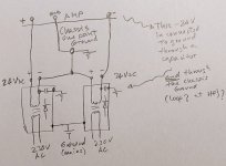
Hope the sketch here may explain my point better. I really don't know if some nF ceramic capacitors between negative output and ground could create a high frequency ground loop still audible.
In normal circumstances no, but with a center tap grounded maybe.
I'm planning to keep the meanwell enclosure and to put additional steel around to reduce possible interference.
Attachments
Thanks Dennis Hui, will check this@jdamico : Nice work.
If you haven't seen this yet, please have a look at lhquam's experience with using two very similar meanwell supplies. Very informative.
https://www.diyaudio.com/community/threads/pass-f5m.406472/post-7551325
OK, the SMPS's I used for the Lazy Singing Bush I needed -65V so I had a similar problem as the + was used as audio gnd.
A small capacitor and a resistor was implemented from - to gnd. The reason was to prevent to much static charge to the power transistors on the heatsink. So I guess it could be safe to remove the cap when the SMPS is installed and properly grounded. I removed the resistor as it would burn anyway as it would get 65V. They were smd so I removed them using a heatgun. From memory the cap was removed also as they were very close so the heatgun took them both.
A small capacitor and a resistor was implemented from - to gnd. The reason was to prevent to much static charge to the power transistors on the heatsink. So I guess it could be safe to remove the cap when the SMPS is installed and properly grounded. I removed the resistor as it would burn anyway as it would get 65V. They were smd so I removed them using a heatgun. From memory the cap was removed also as they were very close so the heatgun took them both.
I'm also using two Meanwell LRS-150-24 smps for my M2 clone and didn't have to make any modifications to the Meanwells. I don't hear a high frequency ground loop.My plan Is to cut these two capacitors legs to avoid ground loops in the high frequency because I will make a one point star ground.
Some experience with this issue?
It is right to cut these two caps?
You can read about my build in post #3526, #3531 & #3535.
- Home
- Amplifiers
- Pass Labs
- Official M2 schematic