Andrek,
I don't know what you were doing in 1980 when I was repairing tube televisions, and you said I didn't know how to work on tubes.
And something simpler than this OTL scheme doesn't really exist.
You don't know what a cathode meter is? it is shameful for someone who claims to work on tubes.
I don't know what you were doing in 1980 when I was repairing tube televisions, and you said I didn't know how to work on tubes.
And something simpler than this OTL scheme doesn't really exist.
You don't know what a cathode meter is? it is shameful for someone who claims to work on tubes.
FWIW dept.: there are OTLs that are simpler than this one.And something simpler than this OTL scheme doesn't really exist.
The Atma-Sphere OTLs are simpler. They employ a Circlotron output that is driven symmetrically.I honestly can’t think of any simpler OTL designs. Still no clue what a cathode meter is.
A cathode meter is any device that can tell you what the current through the tube is. So a volt meter across a cathode resistor, or a current meter in series with the cathode.
@CaptainChaos are you able to talk with me in private, about my aresaudio otl amp, thanks.
Attachments
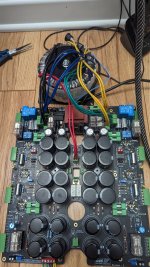
Did you build that ? or is it from Ares. When I first started building my OTL, that was the PCB I tried to get from Ares, but it was unavailable, and still is i think so i went with the 4 separate boards option. That board looks really good and neat, but it will make trouble shooting a little more tricky. What problem do you have with the offset. Is it on both channels, has the amp ever worked, does the speaker protection trip.
i should have a bit more time tomorrow evening, to chat more.
i should have a bit more time tomorrow evening, to chat more.
Yes, i built my myself, write me at my @mail chabotolivier@gmail.com or in private. Thanks
According original 6c33c-(b) datasheet cathodes emission (current) can be checked in this way : https://www.diyaudio.com/community/threads/tube-6c33.387981/#post-7066330
,just to add; measured cathode current have to be relative steady and without gradually current level fall in function of test time .
,just to add; measured cathode current have to be relative steady and without gradually current level fall in function of test time .
Atmospheres, thank you for your reply,The Atma-Sphere OTLs are simpler. They employ a Circlotron output that is driven symmetrically.
A cathode meter is any device that can tell you what the current through the tube is. So a volt meter across a cathode resistor, or a current meter in series with the cathode.
kathodemeter is a device for measuring and controlling tubes, and contains most of the sockets for tubes, but also the possibility to supply with any voltage and current, both positive and negative

hello Banat, many,many thanks for the 6C33C verification scheme.According original 6c33c-(b) datasheet cathodes emission (current) can be checked in this way : https://www.diyaudio.com/community/threads/tube-6c33.387981/#post-7066330
,just to add; measured cathode current have to be relative steady and without gradually current level fall in function of test time .
I built the device and it works very well even with a voltage of 110v.
now I know why my amplifier doesn't work because a 6C33C is not good. (Nobody has suggested to me that this tube is defective)
No problem, because I started to specialize in this OTL
Greetings to all members, Mario.
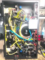
I have problem with my diy project from Aresaudio, after the standby time the speaker protection not allowed to boot the amp, DC ⚡ is present to the ground speaker, i bypass the speaker protection to read the DC ⚡, anybody know why I have dc on my negative speaker terminal ..
https://photos.app.goo.gl/zKpJjjbnvLcgyGA47
https://photos.app.goo.gl/KN5kyKnxkBSVYT9d6
https://photos.app.goo.gl/zKpJjjbnvLcgyGA47
https://photos.app.goo.gl/KN5kyKnxkBSVYT9d6
Attachments
Hi gentlemen,
I'm finally putting together all the stuff.. not an easy task while working and having a girlfriend too")
Anyway, I have some spare time now and I thought I finish my little OTL of Tim Mellow.
Can you please help clarifying some basic things ?
Question1:
In the original article, there's 1 PSU shown, feeding both Left and Right side circuits, right ?
I think schematics is for mono circuit (of course) but the PSU was meant for driving both sides (stereo).
T1 is specified for 15VA ->
for stereo when feeding 2 input tubes (2x 0.37A) and 4 driver tubes (4x 0.22A) altogether, heater current draw is 0.74 + 0.88 = 1.62A (~10.2VA) so we're still good
T2 is specified for 225VA ->
for stereo when feeding 4x 6C33C tubes (4x 3.6A /12Vseries connected in each/), heater current draw is 14.4A -> ~172 VA so this is again ok
T3 is specified for 625VA
for stereo I assume. One side only needs half of this approximately (or even less).
Question2:
I might be in trouble with my transformers. Or even not - can you elaborate the 'issue' if there's any, please ?
To whatever reason, I ordered 4 transformers for this project 3-4 years ago:
T1 (25VA - more than needed)
T2 (250VA - more than needed)
2x T3 (400VA each - less than original but I have 2 of these then, this way more capacity again)
The idea was to have heaters for both sides on common secondaries as in the original article (I assume), but for the anode voltages let's use 2 separate transformers and full circuits behind them.
So far nice, but now comes the trick and my question
Thinking in stereo integrated constellation:
- all 4 driver tubes' heater potential needs to be pushed down to -450V (HT3).
and I have 2 HT3-s, one for Left and one for Right side and one common heater transformer secondary.
- 2 (of 4) 6S33S' heater potential needs to be pushed down to -150V (HT4).
and I have 2 HT4-s, again for Left and Right side - and one common heater transformer secondary.
Which HT3 and HT4 points shall I use for these common fed heaters ? Left or right ?
Can I do it at all without screwing up something ? (E.g. using Left side's HT3 for all affected heatings and Right side's HT4 for all affected heatings).
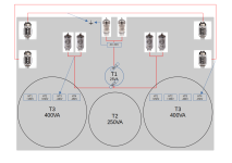
Made a little drawing for quicker understanding.. are the blue arrows (the potential shifts) okay so, as an example ?
(I have 2 T3-s).
I'm finally putting together all the stuff.. not an easy task while working and having a girlfriend too
Anyway, I have some spare time now and I thought I finish my little OTL of Tim Mellow.
Can you please help clarifying some basic things ?
Question1:
In the original article, there's 1 PSU shown, feeding both Left and Right side circuits, right ?
I think schematics is for mono circuit (of course) but the PSU was meant for driving both sides (stereo).
T1 is specified for 15VA ->
for stereo when feeding 2 input tubes (2x 0.37A) and 4 driver tubes (4x 0.22A) altogether, heater current draw is 0.74 + 0.88 = 1.62A (~10.2VA) so we're still good
T2 is specified for 225VA ->
for stereo when feeding 4x 6C33C tubes (4x 3.6A /12Vseries connected in each/), heater current draw is 14.4A -> ~172 VA so this is again ok
T3 is specified for 625VA
for stereo I assume. One side only needs half of this approximately (or even less).
Question2:
I might be in trouble with my transformers. Or even not - can you elaborate the 'issue' if there's any, please ?
To whatever reason, I ordered 4 transformers for this project 3-4 years ago:
T1 (25VA - more than needed)
T2 (250VA - more than needed)
2x T3 (400VA each - less than original but I have 2 of these then, this way more capacity again)
The idea was to have heaters for both sides on common secondaries as in the original article (I assume), but for the anode voltages let's use 2 separate transformers and full circuits behind them.
So far nice, but now comes the trick and my question
Thinking in stereo integrated constellation:
- all 4 driver tubes' heater potential needs to be pushed down to -450V (HT3).
and I have 2 HT3-s, one for Left and one for Right side and one common heater transformer secondary.
- 2 (of 4) 6S33S' heater potential needs to be pushed down to -150V (HT4).
and I have 2 HT4-s, again for Left and Right side - and one common heater transformer secondary.
Which HT3 and HT4 points shall I use for these common fed heaters ? Left or right ?
Can I do it at all without screwing up something ? (E.g. using Left side's HT3 for all affected heatings and Right side's HT4 for all affected heatings).
Made a little drawing for quicker understanding.. are the blue arrows (the potential shifts) okay so, as an example ?
(I have 2 T3-s).
Attachments
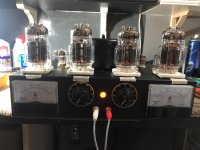
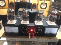
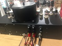
Finally finish, I just make the first fire up regulate the amp to 200Ma and the offset to 0volt, everything looks like ok, so after 30 min I connect a not important speaker, you know just in case, connect a flac player and very nice and clean sound comes up, of course I will test much better on the following days. I strictly follow Tim schematic, I just add a soft start unit for the Antek toroidal AN-64115, I also add a fuse on the speaker path, and other small things like keep the socket of the 6c33c elevated from the enclosure, anyway I will tell more later, thank you to all the suggestion and consideration in this forum....all the best
Attachments
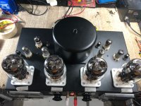
Nice build, you also chose the Winged C-s instead of EF86s (same, I know). Same sockets, same elevation method like in my case
Cool Do you have other transformers too ? How big is this one here ? And what's the transformer's temperature after 1 hour on room temp ?
Mine isn't assembled yet, in progress.
Cool
Do you have other transformers too ? How big is this one here ? And what's the transformer's temperature after 1 hour on room temp ?Mine isn't assembled yet, in progress.
Hi Vortex, the main transformer is the Antek AN-64115 with the SS-12 Soft Start Module, and the CA-005 Steel Cover, the other is the AS-2212 all from Antek, yes I use 6J32P and 6N2P, temperature after 5 hours is very promising, I haven't yet measure it but just by the touch of my hands is very reasonable, but I will measured it and let you know, what I noticed is that the enclosure must be close in the bottom, in this way the fresh air from the fan is forced to go all over and come out from the socket elevation, I also try to leave the bottom open and the temperature of the chassis got much higher, all the best
Attachments
- Home
- Amplifiers
- Tubes / Valves
- OTL designed by Tim Mellow with 4 6C33C?