Yeahh i did a LT spice simulation as well as on multisim, can confirm it triggers at 4volts dc, only for +v not for negative, and since i want to use it with the Discrete amp, i am now going to use UPC1237 with SSR, or a Discrete detector with SSR. Though getting the SSR and the suitable optocoupler is little more expense but i guess in the long run its better.I can confirm that it's more than 1,5V. The exact value I don't remember, too...
My assumption is that here Mauro had tried to optimize between a still practically acceptable level and a safe dynamic headroom so as not to intervene too fast with real music.
I can confirm that it works quite well in practice. it's rare that the error would manifest like a 4V DC stable level ..
Are there in circulation other, more precise circuits? Today I would say yes.
Other 'feature' of the MyRef protection circuit is the insensitivity for negative polarities..
Thank you for editing and removing possible helpfull options. I did read that thread before you edited it...checkout UPC1237 circuit , it can detect both positive and negative threshold ,IC available for 50 Rs in lamington or fully assembled for 300 Rs in Delhi market
Absolutely!i just wonder if this still good to build now
Best (biased) if in his latest version, the My_Ref Fremen Edition.
")
Is there a benefit in running the current pump in inverting mode or using an inverting output stage, thus switching the driving opamp input pins?
I'm ok with 'it sounds better', but if there's a technical reason to it I'm curious to know. I couldn't find a satisfying answer in this thread or Mauro Penasa's documentation.
I'm ok with 'it sounds better', but if there's a technical reason to it I'm curious to know. I couldn't find a satisfying answer in this thread or Mauro Penasa's documentation.

a short quick translation of the relevant pass:
"
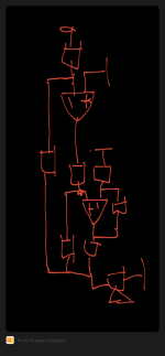
The non-inverting input, unlike the standard inverting configurations, is connected to the NFB network. Using a current pump inverting you get the same result (global) of a non-inverting connection. This kind of connection, that you can define “floating” due to the lack of classic "virtual ground" on the inverting input, has some advantages over one non-inverting normal:
1. The sequence of 2 inverting active stages allows you to use various techniques of compensation, and in favor of global stability and to "align" some related phases.
2. The connection of the input signal on the (-In) allows you to make the most of the internal characteristics of OPAMPs, which they tend to be more linear in this one configuration. (This is not an absolute rule, and varies greatly from case to case)
3. The "floating" condition facilitates the front- end in the process of "tracking" the voltage non-linearities present on the output load."
"
The non-inverting input, unlike the standard inverting configurations, is connected to the NFB network. Using a current pump inverting you get the same result (global) of a non-inverting connection. This kind of connection, that you can define “floating” due to the lack of classic "virtual ground" on the inverting input, has some advantages over one non-inverting normal:
1. The sequence of 2 inverting active stages allows you to use various techniques of compensation, and in favor of global stability and to "align" some related phases.
2. The connection of the input signal on the (-In) allows you to make the most of the internal characteristics of OPAMPs, which they tend to be more linear in this one configuration. (This is not an absolute rule, and varies greatly from case to case)
3. The "floating" condition facilitates the front- end in the process of "tracking" the voltage non-linearities present on the output load."
in the second point he very probably points to the input common mode surpression capability of the opamps.
In my personal opinion, the worst offender in this sense is properly the LM3886. It's parameters, like PSSR for negative supply, and CMMR at the input are orders of magnitude worse than that of the input opamp. Using it in inverting mode eliminates the common mode component on it's inputs, and thus helps greatly to achieve the final very good distorsion values of the composite amplifier.
In my personal opinion, the worst offender in this sense is properly the LM3886. It's parameters, like PSSR for negative supply, and CMMR at the input are orders of magnitude worse than that of the input opamp. Using it in inverting mode eliminates the common mode component on it's inputs, and thus helps greatly to achieve the final very good distorsion values of the composite amplifier.
I agree that the PSRR of the controlling opamp is responsible for the good performance that can be had from a composite amp and also that the PSRR of the LM3886 could be better. I further agree that you can eliminate or reduce CM distortion by using the LM3886 in inverting mode. However, if you normalize the gain (i.e., use -20 V/V in the inverting amp and +20 V/V in the non-inverting amp) the difference between inverting and non-inverting is actually pretty small. I doubt you'd be able to measure a difference between two well-designed composite amps where one uses the LM3886 inverting and the other non-inverting. After all, the distortion of the LM3886 within the composite amp is reduced by the AVOL of the controlling opamp; so by 120-140 dB if you use a modern opamp.
Tom
Tom
Yes, the influence of the common mode errors at the input depends on the common mode voltage excursions present at the inputs. In case of less common mode signal the errors are less. In the general example that You brought up with standard, ~higher gain in the output stage (20V/V) --the input signal is lower, the problem of common mode errors are minimized. So there is no big difference between inv/ noninv. configuration.
But, let's have a look at the actual case of the MyRef topology. The output stage is a current pump, with a Gm close to 1 (by design) .. So the actual 'Voltage Gain' in the stage is dependent also on the Load, let's say 4ohm (like in my typical case..).
The Gain of the stage is:
Vout =Vin* Gm* Rload
A= Vout/Vin = Gm* Rload; if Rload =4
then
A = 4 in case of MyRef Classic
A = 6 in case of FE config
What I wanted to point out is that in this topology the output stage have less gain than what You supposed to have. So common mode is more of a problem. Difference between inverting/ noninverting output stage could be more relevant.
Last part is that in certain variations (Rev C..) there is some open loop gain limiting applied as compensation, for the LM318. And anyway, LM318 is not properly the same capability (Aol) as the latest modern chips..
So the original reasoning of Mauro definitely had it's good foundations with the applied inverting/ inverting topology..
All the best, George
As Tom pointed out above, the CM errors of the current pump make little difference because the current pump is inside the global feedback loop, and the upstream opamp provides loads of gain to correct these errors. Also, In Mauro's schematic, the current pump's opamp (the 3886) sees equal impedances on its inverting an non-inverting inputs, which minimizes the CM errors before the global feedback is applied.in this topology the output stage have less gain than what You supposed to have. So common mode is more of a problem. Difference between inverting/ noninverting output stage could be more relevant
Where CM errors do matter, however, is at the MyRef's input. While the 318's differential input signal is small, its CM signal is basically the amplifier's input signal. One way to deal with it is to make MyRef inverting. Another is to use a "better" opamp (e.g. with a cascoded input stage like OPA627, or something like OPA1641 which minimizes CM errors in a different way) instead of the 318, but this would require a different frequency compensation.
How would you do that?One way to deal with it is to make MyRef inverting.
I would say that one can play with this configuration, but maybe it would be useful to declare what kind of result should be achieved..
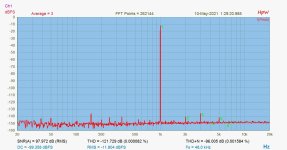
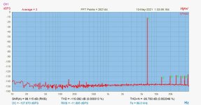
For comparison, here it is a not-so recent test of an experimental configuration of the original topology, a bit modified compensation, a bit modified gain and a different opamp in input (ADA4898) (-because it was actually on the board..)
Halving the gain brought the strongest contribution, decrease in THD.
(applied power in the test was: 8,5Vrms output on 5ohm >> 14,5W)
Attachments
Last edited:
- Home
- Amplifiers
- Chip Amps
- My "audiophile" LM3886 approach