
Since you have a good alternative for the weak NoDAC as output stage, I suggest you don't go modify the 6V6 to noNFB max gain before you install in it a good quality volume pot so you also test it as a line preamp for all your sources first. Has proper gain for line preamp use as it is with NFB resistors.More or less the same gain that I have with the 12B4 x6,5 that I'm just listening now with the bias you adviced B+ 160V 15mA CCS, sounds wonderful.
@Nikos made a very good 6V6 preamp construction indeed.is very very good
Hi, I've just finished making the preamp with AZ1 as rectifier tube and final stage on the power supply as suggested by Elvee. The sound that comes out is wonderful but from the beginning I came across a perpetual hiss that grows when turned on and then tends to stabilize.
I tried various tricks but they didn't work: I didn't take measurements but it doesn't seem like ground loop noise or insufficient PSU filtering.
The noise seems to increase with the potentiometer (power amp) and with the shorted inputs it doesn't change, any suggestions about it? I thought it might be D.H. rectifier (used in hybrid mode with pair of diodes).
Trouble shooting is one of two things:
1. Troubleshooting with a correct schematic in hand.
Please post your schematic, Some of us are not going to read through 4,604 posts in order to find what version of that preamp you are using.
Thanks!
2. A Blindfolded Archer shooting arrows and trying to hit the target.
1. Troubleshooting with a correct schematic in hand.
Please post your schematic, Some of us are not going to read through 4,604 posts in order to find what version of that preamp you are using.
Thanks!
2. A Blindfolded Archer shooting arrows and trying to hit the target.
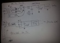
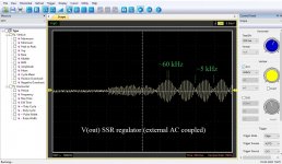
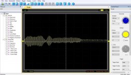
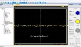
I carry some measurements after the regulator, and at the output channel. I hope I took them right.
Particularly in the former there seems to be a periodic frequency alternation (as with wave beats?). I don't know how to interpret this though...
Particularly in the former there seems to be a periodic frequency alternation (as with wave beats?). I don't know how to interpret this though...
Attachments
Hi Salas, you are right. Beyond other hypothesis I had this suspect me too, and you confirmed.
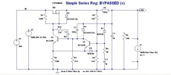
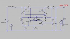
In fact just replacing the regulator with a plain R-C filter (1k-220uF) the preamp is silent. What was wrong with the SSR suggested by Elvee? I followed his schematic, I changed only the Zd (I had that value) and the lower resistor network...
In fact just replacing the regulator with a plain R-C filter (1k-220uF) the preamp is silent. What was wrong with the SSR suggested by Elvee? I followed his schematic, I changed only the Zd (I had that value) and the lower resistor network...
At least you got a simple working solution until sorting out the Elvee reg.In fact just replacing the regulator with a plain R-C filter (1k-220uF) the preamp is silent.
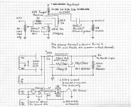
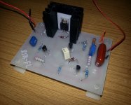
Can you show the modified schematic, and post a picture of the physical build?Hi Salas, you are right. Beyond other hypothesis I had this suspect me too, and you confirmed.
In fact just replacing the regulator with a plain R-C filter (1k-220uF) the preamp is silent. What was wrong with the SSR suggested by Elvee? I followed his schematic, I changed only the Zd (I had that value) and the lower resistor network...
This regulator has been tried by a number of members, and is normally not very demanding
- Home
- Amplifiers
- Tubes / Valves
- 6V6 line preamp