40cm/sec can be cut in Extreme cases over a narrow frequenceband. See Shure Test Record TTR-103. There is a mix of 1kHz and 1,5kHz cut with 40cm/sec. My Atlas Lambda pulls out 0,56mV @ 5cm/sec. So 40cm/sec is 8 times more then that. In extreme cases we can expect 4,48 mV.
150/4,48=33. Overload margin is ca. 30dB.
150/4,48=33. Overload margin is ca. 30dB.
That as far away from where I was as possible I think!I am in Kerala District. Tomorrow we go to Alleppie ( Snake Boat Neru Competition) and then to Cotchie from where we fly home on sunday over Djidda.
Nice info above. I really should educate myself on these matters. I still consider the BC550 as a good low noise. Maybe because I have a box of them ;-).
Jan
Joachim,
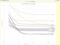
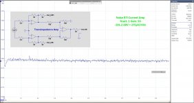
Don’t know how you got these noise images, but they are a bit odd.
As a reference: the AD797 has a documented and measured ca. 1.5nV/rtHz@20Hz where your graph shows 3 times as much with 4.5nV/rtHz.
Fifteen different ZTX851 samples measured less then 0.3nV/rtHz@20Hz where your graph shows 2.2nV/rtHz , even a factor 7 higher !!
Above 100Hz, the two above samples seem to be fine in your graph.
Hans
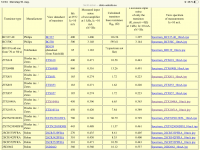
In fact the origin of these tables and graphs is in the Netherlands, so they must be trustworthy :
http://www.dicks-website.eu/low_noise_amp_part3/part3.html
http://www.dicks-website.eu/low_noise_amp_part3/part3.html
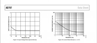
Here's a copy of the AD797 documentation showing 1.5nV/rtHz@20Hz and a copy of a measurement done with the ZTX851 showing less then 0.3nV/rtHz@20Hz.In fact the origin of these tables and graphs is in the Netherlands, so they must be trustworthy :
http://www.dicks-website.eu/low_noise_amp_part3/part3.html
Two ZTX trannies in parallel per input amp. giving a noise improvement of 3dB per amp Two amps in a balanced config causing 3dB additional noise.
So, the remaining noise just that of one single ZTX 851.
I will reproduce Dick's measuring circuit diagram in LTSpice and see what it brings.
One thing is already obvious, measuring transistor noise with a Cap in series with the base will result in wrong results at LF.
Hans
Attachments

Did you see his investigation on AD797 ?
http://www.dicks-website.eu/low_noise_amp_part2/part2.html
http://www.dicks-website.eu/low_noise_amp_part2/part2.html
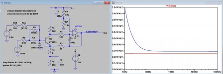
I made a quick LTSpice copy of Dick's model, of course with an ideal input cap which is definitely better that any physical one, and simulated with and without input cap. In both cases output voltage was held at 6 Volt DC.
It's quite obvious that an input cap pollutes the LF noise figure, red line without and blue line with input cap.
Hans
It's quite obvious that an input cap pollutes the LF noise figure, red line without and blue line with input cap.
Hans
Attachments
According this datasheet the BFW16A is a multi emitter versionI have worked on the modified circuit a little and have drawn it better. RB can safely be 68kOhm because hFE of the ZTX1051A is 10x higher then in the BFW16A. Now come new interesting questions. How high is the input Impedance and how high is the overload margin ?
https://pdf1.alldatasheet.com/datasheet-pdf/view/22006/STMICROELECTRONICS/BFW16A.html
concerning striving for lowest noise phono stages please check out post #59 under
https://www.diyaudio.com/community/threads/riaa-amp-using-shunt-feedback.249557/page-3
and post #2+8 under
https://www.diyaudio.com/community/...king-in-inverted-mode-not-to-find-why.222677/
I looked at it and don’t agree with the calculation.Did you see his investigation on AD797 ?
http://www.dicks-website.eu/low_noise_amp_part2/part2.html
When done correct, you won’t get a measured value below the specified 0.9nV/rtHz.
Hans