In reply to Kipman, post 2460:
You're right. That remains to be seen. So far, the whole shabam its just a "paper tiger".
But its great fun, is'nt it ?
Another good question would be: Where will the wired-out-of-phase (notch) frequency be ?
I dont know about 17,2 Khz, or how you get to that figure, but the Hornresp sim. shows a top dip at 5Khz for L=25mm (see post 2446 above), and 4,2Khz using L=30mm. So there is a showstopper at large, overruling the 1/4 wave thing you mention.
ID 12 to 14mm ports should be "acoustically invisible", being only a fraction of the shortest wavelength
When I get those Peerless TC5FC07-04 I think I will start out doing the Vtc studies, as for Rashorn1, to see what we can expect for a top resonance.
This time concentric only, since the main reason for using such small drivers is the possibility of controlling the very top.
Somebody else mentioned the problems of mating a monopole bass to horn mids and treble and I heartily agree. I was reminded of my first Unity setup with monopole bass. Now it's dipole and there's no going back--until I have the room to try out my plane-wave/active-echo-cancellation bass idea.
John"
The problem being the omni-directional nature of monopoles?
Giri,The problem being the omni-directional nature of monopoles?
You are asking "Patrick Bateman", whose real first name is John, about an observation shared by "hancock" (first name John) on the High Efficiency Speaker Asylum 20 years ago.
Among MEH (multiple entry horn) users, you probably will find more advocates of multiple monopole subwoofers to reduce low frequency room mode problems than those using dipoles.
Art
Seems to me to be a matter of ~matching acoustic damping based on the pioneers using dipole woofer bass to mate to the HF horns; I mean what's a horn but a driver in a large folded up baffle?The problem being the omni-directional nature of monopoles?
")
The woofer in a three way MEH often uses a bass reflex alignment, so no.Does the 2*Fs/Qes formula apply to the woofer in a 3 way synergy horn?
http://www.loudspeakerdatabase.com/Ciare/NDI_2.25
https://en.toutlehautparleur.com/pair-of-speaker-ciare-ndi2-25-8-ohm-2-inch.html
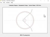
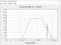
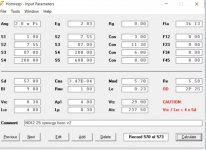
New candidate, small, strong and looks like it can reach high in a quick sim.
https://en.toutlehautparleur.com/pair-of-speaker-ciare-ndi2-25-8-ohm-2-inch.html
New candidate, small, strong and looks like it can reach high in a quick sim.
Tiny horn with the Ciare NDI2-25 x 4. Might be possible to combine with this tiny compression driver.
https://en.toutlehautparleur.com/compression-driver-sica-cd40x70-26-n35-8-ohm-1-0-inch-throat.html
Or maybe I’m delusional..
https://en.toutlehautparleur.com/compression-driver-sica-cd40x70-26-n35-8-ohm-1-0-inch-throat.html
Or maybe I’m delusional..
Attachments
Isn’t it visible? Or is it only me that reads Hornresp like the matrix code.Great find! Mind sharing the sim?
The thing is that I’m doing the sim on my phone controlling a remote computer via VNC viewer. So to export the sim record is way more effort than a screenshot.
It's visible, but your specs aren't right.Tiny horn with the Ciare NDI2-25 x 4. Or maybe I’m delusional..
Last edited:
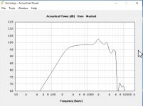
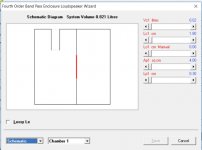
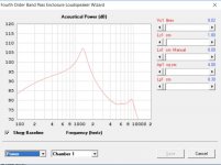
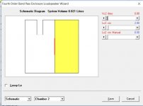
Thanks for the fact check!At a glance, didn't seem good to 1 kHz, but based on this BP4 it will if the tiny chambers can be made.
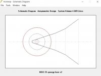
I actually came to a similar conclusion regarding the tiny back chamber on the next test I did. This time I went for a better loading/efficiency.
Attachments
Does the 2*Fs/Qes formula apply to the woofer in a 3 way synergy horn? To the chagrin of the original designer I’m looking into using an alternate woofer for the parts express speaker gallery synergy horn.
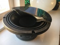
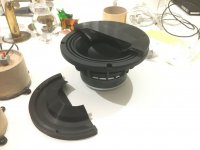
Keep in mind that in the era of 3D printing, you can use a lot of midranges and midbasses which wouldn't work otherwise.
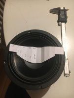
My current project uses the $12 MCM 55-1870 and I'm getting it to play up to 1500Hz when "technically" it should only work up to 173Hz.
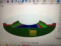
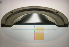
So I'm getting it to play way WAY higher than expected, by using a 3D printed phase plug.
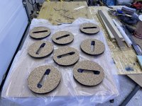
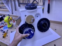
So true! I made a volume filler for my lower mids and I haven’t even tried the raw driver on the horn yet. I figured it couldn’t hurt the response and it randomized the path length to the port.Keep in mind that in the era of 3D printing, you can use a lot of midranges and midbasses which wouldn't work otherwise.
My current project uses the $12 MCM 55-1870 and I'm getting it to play up to 1500Hz when "technically" it should only work up to 173Hz.
So I'm getting it to play way WAY higher than expected, by using a 3D printed phase plug.
Attachments
-
 1E19EB23-C49A-40A0-A7D1-0AF6D2DB4F92.jpeg269.3 KB · Views: 170
 -
 F44CBE9D-60B2-4B1D-A86F-25AA61DFBB61.jpeg626.7 KB · Views: 160
 -
 4B39CF2E-4B44-4844-9CFE-D55C0EA88176.jpeg342.9 KB · Views: 172
 -
 69801729-D1EB-4381-8004-06CA1959DCEC.jpeg273.6 KB · Views: 179
 -
 A50EB496-B7D3-4E02-9CF3-3F718F0316A0.jpeg216.7 KB · Views: 188
 -
 19B7AFB9-662B-426D-835F-9344E50C1628.jpeg818.6 KB · Views: 179
 -
 FFD87D0A-5B77-42AA-83D6-A1580E39AA2A.jpeg426.5 KB · Views: 176
Reducing VTC by filling the cone profile of a 5" should make it reach into the >1kHz range, what "technically" would low pass a 5" driver in a MEH to only 173Hz?My current project uses the $12 MCM 55-1870 and I'm getting it to play up to 1500Hz when "technically" it should only work up to 173Hz.
So I'm getting it to play way WAY higher than expected, by using a 3D printed phase plug.
What phase plug design are you using for the MCM 55-1870 to reach 1500Hz?
- Home
- Loudspeakers
- Multi-Way
- Suitable midrange cone, for bandpass mid in Unity horn.