Hmm interesting. Tim said in the article it's a class A amp:
If you can increase the load to between 40 and 100Ω, then you can easily obtain 50W of pure class A power.
Pure class A at 50W ?
No, he says for 40... 100 ohm load.
Are your speakers 100 ohm or 40 ?
Rather 8 ohm, right ... P = R * I * I that makes all the difference.
If you bias the tubes at 200mA you can only swing the current through the tubes 200mA up and 200mA down (!) before one of them reaches zero, and thats when you leave class A.
Because class A demands that both tubes in a push-pull conduct all the time.
So total swing in class A is 2x200mA, P = 8ohms * 0.4A * 0.4A = 1.28Watts (!)
Bias at 400mA and get 4 times the power namely P = 5.12Watts in class A
Bias at 350mA and 100ohm speakers gives P=100*0.7*0.7=49W ... this is the marketing figure Tim used in the article ...
One last question: input sensitivity.
The article was written "some time ago".. but nowadays I see the trend of having DAC-s which have Line-Out level of 2V for RCA and 4V for XLR connections.
I myself also use a little Topping E30 with a very good sound and the next one will be something similar.
The original article says:
I assume I have to adjust resistor values to lower gain (?) so I get this same 25W into a 8 Ohm load at 2V (instead of 500mV) when unbalanced. For PRE-IN. (I'm planning having 2 unbal. inputs, one with attenuator and one without). For the attenuated input, is it enough to use a different impedance volume pot ? But for the direct input without pot, the previous question is still valid.
In both cases I'd like to avoid overdriving input stages or the whole amplifier.
Any ideas on these ?
The article was written "some time ago".. but nowadays I see the trend of having DAC-s which have Line-Out level of 2V for RCA and 4V for XLR connections.
I myself also use a little Topping E30 with a very good sound and the next one will be something similar.
The original article says:
The signal from input phono socket SK1 is fed to the grid of V1a via the volume control RV1, C1, and R1. Shunt feedback is provided by resistors R1 and R3, which mix the output and input signals to set the overall maximum gain to a value of R3/R1, which is about 29. In other words, an input voltage of 500mV is required to produce 25W into an 8Ω load. When RV1 is set to maximum, the input impedance is about 26k due to RV1 in parallel with R1.
I assume I have to adjust resistor values to lower gain (?) so I get this same 25W into a 8 Ohm load at 2V (instead of 500mV) when unbalanced. For PRE-IN. (I'm planning having 2 unbal. inputs, one with attenuator and one without). For the attenuated input, is it enough to use a different impedance volume pot ? But for the direct input without pot, the previous question is still valid.
I'd put 2 XLR connectors onto the amp too, switchable. Not sure how it will behave in such a case (meaning input level) if I apply this trick as well, in this case I'm fed by a 4V output on DAC side. (Again, direct input, no attenuator).Of course, you could achieve excellent noise immunity by using a preamplifier with a balanced output and then applying this to both grids of V1 via C1 and C2.
In both cases I'd like to avoid overdriving input stages or the whole amplifier.
Any ideas on these ?
One last question: input sensitivity.
I'd put 2 XLR connectors onto the amp too, switchable. Not sure how it will behave in such a case (meaning input level) if I apply this trick as well, in this case I'm fed by a 4V output on DAC side. (Again, direct input, no attenuator).
In both cases I'd like to avoid overdriving input stages or the whole amplifier.
Any ideas on these ?
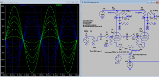
Looking at the schematic it's a SE input with a LTP phase splitter on the front.
Look at it like this - the tubes don't know it's balanced and only see the larger 4V signal. So those input tubes potentially will see the full 4V signal on the grids depending on volume setup.
LTP is basically the differential piece of an opamp. As such you should then get a corresponding differential output. The size depends on the design.
The NFB is the differential so I suspect the LTP would compare only one part of the XLR signal against the differential. Thus I'd expect a 4V XLR signal is being compared against a 2V differential output.
The M60 has an SE RCA that attaches to the XLR, the rest of the system is balanced and has a feedback for each phase from the circlotron outputs to the LTP at the front - thus essentially compares XLR input pin to the corresponding output pin. The resulting signal is only produced at the output by the difference between the two XLR pins.
Last edited:
I was looking at this - sounds like I have the wrong schematic?
I have found on google what seems to be a balanced from page 2 of this thread which would work but it has a B+ rail based feedback network so I don't think it's the Tim Mellows' design without modifications.
Apologies - I forget to say - yes adding the XLR inputs to both sides of the LTP will cancel common noise and will act like a differential input I may have missed a feedback loop (perhaps through the rails).
Last edited:
Well, I took the schematics from this article.
And here Tim Mellow states in the circuit details:
"Of course, you could achieve excellent noise immunity by using a preamplifier with a balanced output and then applying this to both grids of V1 via C1 and C2."
I think he mentiones end-to-end noise immunity, not the amplifier itself. It's a push-pull but Class A only (apparently) for the first watts, above this it's Class B. A fully Class A pushpull amplifier could be split into 2 SE parts, driven by balanced XLR inputs and hence serve as a fully balanced amplifier, but this is not the case here.
So it's neither a fully (all the way up with power) Class-A amp, neither single-ended (because we talk about push-pull all the time). If pushpull, that's good but due to leaving Class-A with increasing power (at 8 Ohms), it cannot be 'converted' to a fully-balanced Class-A amp with 2 SE rails for +/- signals.
I assume he knows what he stated in his article, so the question is not if one has the right or wrong schematics but the fact itself that it could be driven in a balanced way and HOW this balanced input alternative behaves regarding voltage levels when I connect a Topping D90's XLR output to the OTL amp.
Edit: read your update, ok. Cheers)
And here Tim Mellow states in the circuit details:
"Of course, you could achieve excellent noise immunity by using a preamplifier with a balanced output and then applying this to both grids of V1 via C1 and C2."
I think he mentiones end-to-end noise immunity, not the amplifier itself. It's a push-pull but Class A only (apparently) for the first watts, above this it's Class B. A fully Class A pushpull amplifier could be split into 2 SE parts, driven by balanced XLR inputs and hence serve as a fully balanced amplifier, but this is not the case here.
So it's neither a fully (all the way up with power) Class-A amp, neither single-ended (because we talk about push-pull all the time).
If pushpull, that's good but due to leaving Class-A with increasing power (at 8 Ohms), it cannot be 'converted' to a fully-balanced Class-A amp with 2 SE rails for +/- signals. I assume he knows what he stated in his article, so the question is not if one has the right or wrong schematics but the fact itself that it could be driven in a balanced way and HOW this balanced input alternative behaves regarding voltage levels when I connect a Topping D90's XLR output to the OTL amp.
Edit: read your update, ok. Cheers
)Well, I took the schematics from this article.
And here Tim Mellow states in the circuit details:
"Of course, you could achieve excellent noise immunity by using a preamplifier with a balanced output and then applying this to both grids of V1 via C1 and C2."
Yep that is precisely the way you'd do it.
The input tube and amp gain states 500mV for 25W, so you'd be reducing the volume (that would be needed on both inputs).
I think he mentiones end-to-end noise immunity, not the amplifier itself. It's a push-pull but Class A only (apparently) for the first watts, above this it's Class B. A fully Class A pushpull amplifier could be split into 2 SE parts, driven by balanced XLR inputs and hence serve as a fully balanced amplifier, but this is not the case here.
From my understanding it will operate in class A and AB2 as push pull. Essentially the the push pull always operates until the tube clips (ie "enters" AB2). So whilst the signal is amplitude is under a certain level it can be handled on both upper and lower tubes. When the amplitude clips on one, the other continues to take over - that clipping point is set so that it's not 0V. It's a good way to get more power being more efficient. However as the tube cuts off, the output impedance that the load sees changes. It's like switching off a resistor path in a resistor divider.
Broskie writes about this with a hybrid totem design called the "Brazilian OTL", the solid state followers are setup so they don't switch off at a point that causes output impedance shifts.
So it's neither a fully (all the way up with power) Class-A amp, neither single-ended (because we talk about push-pull all the time).
That's ok - A/AB is good. You can be SE input/output and class A and push pull
follower designs follow the opposite phase output of the SE to give a 'push-pull' but that's a different discussion. I assume he knows what he stated in his article, so the question is not if one has the right or wrong schematics but the fact itself that it could be driven in a balanced way and HOW this balanced input alternative behaves regarding voltage levels when I connect a Topping D90's XLR output to the OTL amp.
Edit: read your update, ok. Cheers
It would be possible to add additional feedbacks into the design too - it's just that as it stands the feedback is only SE.
Last edited:
Thanks NickKUK, so in general, if I want to feed the amp with input levels above 500mV, I need to drop some voltage first.
Which would be the most elegant via reducing the input tubes' gain maybe.
Looking at the EF86, the input grid range to that is relatively small but factor in negative feedback. The ecc83 is a 100mu tube with a 0-4V grid so you may need look at that if the input is 4Vpk (rather than 4Vpp) unless you voltage divide it down. The EF86 has about 4Vpp so the ECC83 is providing the 500mVpk to 2Vpk.
Fastest route would be to volume reduce before the input tube. Longer term you could replace the ecc83 with a lower mu tube with some possibly knock on changes however this would change the sound.
Last edited:
Okay, so just to make clear:
RCA out - 2Vrms = a little more than 2Vpk, right ?
XLR out - 4Vrms = a little more than 4Vpk, right ? (Which equals then to 8+ Vpp)
Using lower mu tubes was also my idea. Looking at E88CC and especially my favourite, the 6N1P, Av=33 instead of 100.
RCA out - 2Vrms = a little more than 2Vpk, right ?
XLR out - 4Vrms = a little more than 4Vpk, right ? (Which equals then to 8+ Vpp)
Using lower mu tubes was also my idea. Looking at E88CC and especially my favourite, the 6N1P, Av=33 instead of 100.
Okay, so just to make clear:
RCA out - 2Vrms = a little more than 2Vpk, right ?
XLR out - 4Vrms = a little more than 4Vpk, right ? (Which equals then to 8+ Vpp)
Using lower mu tubes was also my idea. Looking at E88CC and especially my favourite, the 6N1P, Av=33 instead of 100.
I was taking your RCA/XLR taking that as Vpk. rather than Vrms/Vpp. Vpk is what the tube will see when fed into the grid.

Line level - Wikiwand
Vrms = Vpeak/1.414. So peak is larger than Vrms.
You could make the tube frontend a near buffer stage, so it provides the high input impedance and drives the pentode drivers. Try it with the standard design first, then modify it. There will be enough fun with getting the tubes all tuned up.
Last edited:
To reduce gain in front LTP just insert cathode resistor of equal value to each leg with out affect the anode voltage that set the bias of entire stage. When the gain is reduced you need to increase gNFB to maintenance damping factor is also a good way to check which damping factor is best for your speaker.
12ax7 ltp stage has a max. gain of 20, it's possible to reduce it to unity with 20k cathode resistor.
12ax7 ltp stage has a max. gain of 20, it's possible to reduce it to unity with 20k cathode resistor.
Attachments
Vrms = Vpeak/1.414. So peak is larger than Vrms.
You could make the tube frontend a near buffer stage, so it provides the high input impedance and drives the pentode drivers. Try it with the standard design first, then modify it. There will be enough fun with getting the tubes all tuned up.
Well, aforementioned DAC is peaking at almost +/- 6 Volts on XLR (4Vrms), so I might really need to lower gain and see where I arrive then for driving the EF86.
Well, aforementioned DAC is peaking at almost +/- 6 Volts on XLR (4Vrms), so I might really need to lower gain and see where I arrive then for driving the EF86.
12Vpp is around +12dBV from a XLR perspective (the differential signal will be less) but the tube sees that on the grid.
You will need to reduce the 12Vpp to fit the input range of the ECC83 or it will clip (regardless of the changes Koonw has proposed). The cathode point will be reduced by the NFB, but not that much given the opposing valve where the NFB is connected also has a limit that it can impose! Only way is a volume pot on both unless the tube is switched for something with a larger input range - however we're not going to go down that route on this thread.
Both input and NFB still have to fit into the non-distorting area of the ecc83.
Koonw's reduction reduces the output voltage of the LTP. This makes it less sensitive but has a couple of caveats:
* My understanding is LTPs like large Ra values that gives the best differential balance.
* It doesn't change the input grid limitations
* This also changes the operating point and steepens the line thus you may find the input range drops to stay out of the the distorting areas (ie near 0-1mA for example).
I'd be tempted to rip out the EF86 and see if an EF89 could be replaced instead - it's grid range is far larger but it has a larger current draw. No idea if it could but worth exploring if it's available, there may be other tube better suited. It would definitely need a PSU updated.
Last edited:
That is because 470k is still a poor constant current source, try with a real CCS.Code:My understanding is LTPs like large Ra values that give the best differential balance.
I was going to suggest a CCS on that but I thought we were into enough complexity
It should also help flatten the load line 
Last edited:
You can stay with 470k as long as cathode resistor (e.g <20k) does not cause too much unbalance. The 2 cathode resistor need not be identical for gain reduction, the one on the input side detect the gain. That is all I know: one is ground cathode amp the other is cathode follower the gain is slave to other one, not by the cathode resistor. In this amp, the cathode resistor to be added should be same so the anode voltage is same.
Last edited:
Uh Gents, that's already Chinese talk to me. If reducing gain is so complex here, I really better stick to the volume-pot based original setup and maybe lower RCA + XLR input signal level (in PRE-mode) with a voltage divider before. That might be weird at first sight, but given the complexity a gain change introduces, uh, it's the easier route for me right now, apparently.
- Home
- Amplifiers
- Tubes / Valves
- OTL designed by Tim Mellow with 4 6C33C?