I don't understand the question "measure at every point in a room" does not equate to "Mic axis angle random to speaker axis?"
Earl so how you want exactly place pressure field mic?
I am still not sure that I understand. If measuring the free field response of a loudspeaker the mic is just placed in a space a meter or more from the source.
If you mean measuring room response then that's a completely different thing. To get a stable result you must use spatial averaging, typically in a space a few feet wide. At LF this is not really a requirement since the response won't vary much through a small space.
If you mean measuring room response then that's a completely different thing. To get a stable result you must use spatial averaging, typically in a space a few feet wide. At LF this is not really a requirement since the response won't vary much through a small space.
The mics directional pattern should not be a big issue for a steady state measurement, but omni response would likely be the better choice.
The comment "If I measure the response at every point in a room" was more hypothetical than something that someone would actually do - I've never done it.
The comment "If I measure the response at every point in a room" was more hypothetical than something that someone would actually do - I've never done it.
If, at the exit of a compression driver a wavefront has been brought together which conforms to a certain angle of radiation, and yet the walls at the exit are at another angle.. should the waveguide added from that point support the wavefront angle, and what are the potential downsides of this scenario?
Technical Note Volume 1 Number 21 - JBL Professional
...has some interesting info on matching driver exit angles to an appropriate horn.
Until the 80s every driver they made had a flare rate <200Hz "based on the exit geometry of the original Western Electric 594 driver".
...has some interesting info on matching driver exit angles to an appropriate horn.
Until the 80s every driver they made had a flare rate <200Hz "based on the exit geometry of the original Western Electric 594 driver".
It's ambiguities like this ") I wanted to draw what I was talking about. Errors of this nature have come up before.
I wanted to draw what I was talking about. Errors of this nature have come up before.
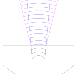
Shown, is a driver with 5 degree walls and an erroneous 14 degree wavefront (it seemed easier to use as an example). Blue shows the waveguide continuing the wall angle but the wavefront is never normal to it. Magenta shows the waveguide supporting the wavefront at the expense of a visual wall discontinuity at the throat transition.
Supporting the wavefront would seem the right thing to do, potentially reducing diffraction compared to the blue option. Apart from this, what negative effects could we expect from the visual wall discontinuity?
I wanted to draw what I was talking about. Errors of this nature have come up before.Shown, is a driver with 5 degree walls and an erroneous 14 degree wavefront (it seemed easier to use as an example). Blue shows the waveguide continuing the wall angle but the wavefront is never normal to it. Magenta shows the waveguide supporting the wavefront at the expense of a visual wall discontinuity at the throat transition.
Supporting the wavefront would seem the right thing to do, potentially reducing diffraction compared to the blue option. Apart from this, what negative effects could we expect from the visual wall discontinuity?
Attachments
I would like to restate a question that I put into the Ath4-thread, where it was presumably ill suited. I have been working on a typical 2-way compression driver + 12-inch PA woofer speaker. Throughout the work I came to know about a couple of deficiencies of the waveguide in use. It is the well know JBL-copy, 90x50 PT waveguide fabricated by Dayton in my case. Many years ago already, Mr. Geddes made a verdict on these waveguides, essentially that they produce a lot of resonances because of diffraction. I identified a couple of other problems too here, but my questions is concerned with another issue:
My main interest in a comparison between axisymmetric and asymmetric waveguides arose from a note by Kimmo Saunisto, when he talked about how to optimize vertical off-axis behaviour in the crossover region. Fluid posted it here, where he brought up kimmosto's 1.2 lambda rule for DI optimized 2-way vertical spacing. Kimmo repeated his lesson recently over at htguide.com forums. Since then, and also because of further limitations of the current device, I want to replace the waveguide in the long term with a custom solution. So I am interested to learn about the pros and cons of something like an OS-SE axisymmetric waveguide and i.e an 90x50 QSC OS waveguide. What can they each do the other does not? The scenarion is home use, the ceilings not very high at 2.7 meters, European city appartment room (not big). Maybe Earl you can say something on this comparison.
To my knowledge, i.e. with axisymmetric devices, there is an on-axis dip in the very center angles. Dispersion slots will always introduce diffraction and therefore HOM if I understood this correctly, but they are a means for widening the high frequency pattern, seems to be a trade off.I would like to know what trade-offs do you see between a rectangular waveguide with high-frequency dispersion slots like Tritonia/M2-style and an axisymmetric OS-SE waveguide?
My main interest in a comparison between axisymmetric and asymmetric waveguides arose from a note by Kimmo Saunisto, when he talked about how to optimize vertical off-axis behaviour in the crossover region. Fluid posted it here, where he brought up kimmosto's 1.2 lambda rule for DI optimized 2-way vertical spacing. Kimmo repeated his lesson recently over at htguide.com forums. Since then, and also because of further limitations of the current device, I want to replace the waveguide in the long term with a custom solution. So I am interested to learn about the pros and cons of something like an OS-SE axisymmetric waveguide and i.e an 90x50 QSC OS waveguide. What can they each do the other does not? The scenarion is home use, the ceilings not very high at 2.7 meters, European city appartment room (not big). Maybe Earl you can say something on this comparison.
I have never been interested in commercial products and even less so now. SO I can't comment on XX12 performance or how it compares to YY10. My expertise is in theory.
Theoretically a square waveguide will have a different directivity along the diagonal that the axis. Hence it is not really constant directivity. Axisymmetric is constant directivity in angle around and with frequency. That's why I use a round waveguide.
There is not necessarily a hole on axis of a round waveguide. It's all in the design. Some of my speakers had it others did not. I know how to eliminate the hole now.
There is nothing that I can add that hasn't been discussed at the ATH thread. There you can find the best waveguide designs possible. What's not to like!
Are you familiar with the case for positioning a dome tweeter offset on a flat baffle to modify the response, compared to leaving it in the middle and rounding the edges?To my knowledge, i.e. with axisymmetric devices, there is an on-axis dip in the very center angles.
In any case the 0 axis region is such a small part of the overall power....
Attachments
Theoretically a square waveguide will have a different directivity along the diagonal that the axis. Hence it is not really constant directivity. Axisymmetric is constant directivity in angle around and with frequency. That's why I use a round waveguide.
I remember a post by P.Bateman now, where he discussed this. And I think you also mentioned this in the PDF when you measured the asymmetric JBL waveguide for Zilch. I still do not perfectly understand what is the calculus of i. e. a JBL PTH-1010HF-X etc. waveguides, though. Is it correct that a rectangular waveguide which features diagonal high frequency diffraction slots such as the mentioned model redirects sound pressure levels to the orthogonal axes, to optimize high frequency response on vertical and horizontal planes, but sacrificing diagonal response?
There is not necessarily a hole on axis of a round waveguide. It's all in the design. Some of my speakers had it others did not. I know how to eliminate the hole now.
Would you mind giving us an idea which factors can be optimized to reduce the on-axis dip?
I remember a post by P.Bateman now, where he discussed this. And I think you also mentioned this in the PDF when you measured the asymmetric JBL waveguide for Zilch. I still do not perfectly understand what is the calculus of i. e. a JBL PTH-1010HF-X etc. waveguides, though. Is it correct that a rectangular waveguide which features diagonal high frequency diffraction slots such as the mentioned model redirects sound pressure levels to the orthogonal axes, to optimize high frequency response on vertical and horizontal planes, but sacrificing diagonal response?
I can't comment on specific designs, particularly ones that I am not familiar with, but what you suggest sounds more like hand-waving to me.
Would you mind giving us an idea which factors can be optimized to reduce the on-axis dip?
If the mouth termination is gradually flared into the baffle with a curve whose slope gradually increases (2nd derivative goes from zero to some finite value - a fixed radius does not do this,) then the hole can be eliminated if the waveguide is large enough. This is all well discussed over in the thread on ATH.
I can't comment on specific designs, particularly ones that I am not familiar with, but what you suggest sounds more like hand-waving to me.
Yes, I think so too. Thanks anyway.
I'd like to ask about a plane wave tube, in the context of it being stuffed and used to dissipate what it is put into it. An example is a lossy tube used to absorb the rear radiation from a driver, similar only in appearance to a transmission line, except non-resonant.
To avoid reflections, is it best to keep the stuffing density consistent along the line, or would varying it help?
Is there a benefit to not stuffing around the driver nearfield, leaving a clear space behind it.. or does this create the opportunity for a reflection when the stuffing is reached?
Is it beneficial to stick with a cross sectional area similar to the cone area?
- Home
- Loudspeakers
- Multi-Way
- Geddes on Waveguides