Hi Rick,
I would argue that you need a buffer after the volume control to deal with cable capacitance and sometimes non-linear input impedance. Yes, it will work without the buffer, but depending on the specifics, it may not be delivering the sound quality you think you are getting.
-Chris
Yes, I agree that the volume control should be followed by a buffer. In my view, it is perfectly OK for the buffer to be a quality audio op amp like the LM4562 or better. I also like to see a series resistor at the output of the op amp to avoid capacitive load instability and to terminate the interconnect in a reasonably low impedance that is maybe within a factor of 2 of the likely characteristic impedance of the interconnect (which usually falls between 50 and 120 ohms).
A little bit more optional is a buffer ahead of the volume control. This permits the use of a lower impedance volume pot without presenting the source with a heavy enough load to compromise its performance, such as compromising bass response in an ac-coupled arrangement. The ability to employ a lower impedance volume control pot will also reduce noise a bit. Having said that, one can often get away with a 50-k volume pot. With a buffer, one might be inclined to use a 10-k volume pot.
I note that many power amps do not have level controls, and those that do do not have those controls ganged to preserve balance.
Cheers,
Bob
A few years ago I build a preamp based on TKD attenuator + BUF 03 ....
Album Archive - My preamp
Details:
A Buffered Headphone Driver. – HeadWize Memorial
Album Archive - My preamp
Details:
A Buffered Headphone Driver. – HeadWize Memorial
Last edited:
Hi,
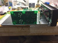
Bob has his amp running and tested it out, as mounted on one heatsink side. Mine is in final assembly.
We evaluated a few transformer options, so I bought a transformer last week. I found a very reasonably priced Triad 500VA/50-0-50V at Arrow which will suit my purposes. Watch out for shipping costs. Arrow shipped mine for free.
Imo we have the basic mechanics of the chassis and pcb figured out. Need to figure out AC supply means. There are a few options available. Was thinking of doing another pcb for that. So moving along but slowly. I am happy that we have the chassis mechanics figured out in that 3Ux300mm chassis. I found the chassis could use a few minor mods to make assembly so much easier, in our case.
We were lucky to get a first rev's of pcb's out without a chassis fit issue. I should have gotten the chassis first before designing the pcbs.
If there is a lot of interest we can start a BC-1 thread.
Rick
Attachments
Last edited:
Hi Von,
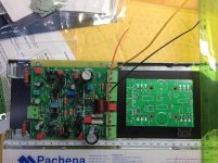
The second round of PCBs for the BC-1 is up and running and undergoing evaluation. Results so far are very encouraging. The second round primarily involved a physical design change to make the boards compatible with a suitable available enclosure. The first round was implemented on two boards. The current second round is implemented on 3 boards (not counting a power supply board). Those are the analog front end (AFE - IPS/VAS), output board (OPS - including drivers and output transistors) and the protection board (PROT).
These are 3 smaller boards whose dimensions are suitable for a 3U enclosure/heatsink arrangement, and provide some physical design flexibility. In a 300 mm deep enclosure, the AFE and OPS will be mounted on the heat sink, with the PROT mounted elsewhere. A third round of PCBs will include minor layout touch-up (likely very minor) and a mirror-image set of boards (at least AFE and OPS) to implement the "other" channel.
Physical design to integrate the board set into the chosen enclosure is ongoing and in an advanced stage. Rick can make better comment on PCB and physical design status. Toroidal power transformer recommendations are also being worked on as part of the physical design process.
Depending primarily on transformer details, the amplifier will deliver at least 150 wpc into 8 ohms. The amplifier has been tested into 8, 4 and 2 ohms.
Time frame? Not yet sure.
Cheers,
Bob
Wow. Sounds like nice progress on the design and layout. Good to hear the OPS boards will be mirror image so the layout of the MOSFETs on the heat sinks will be symmetrical. It appears from the image that 0.22ohm source resistors are being used. Is that correct? If so, what’s the reasoning for the change from the DH220C design? Thanks, Bill.
Hi Bill,
The Lateral MOSFET power amplifiers, like the DH-220 and DH-220C, do not generally employ source resistors, partly because of the inherent temperature stability of lateral power MOSFETs at the quiescent bias current that they are usually biased at.
Amplifiers with BJT output transistors virtually always must have emitter resistors for reasons of bias stability. My favorite value is 0.22 ohms. A higher value will result in less quiescent bias current to satisfy the Oliver criteria, making the small class A region even smaller. A smaller value tends to reduce temperature stability and increase current hogging among paralleled output transistors.
Cheers,
Bob
Hi folks,
In my previous post it's the BC-1 design (bjt-3EF) not the DH-220C, that is another matter, as shown what needs to be done to make it fit the usable heatsink area on the 3Ux300mm chassis
Shown attached is the DH-220CR(OPS) which is the mirror of the original DH-220C(OPS)-B0
The DH-500C(OPS) is the one I am planning to have a mirrored version since it is narrowest and has the 3 pairs.
So what are we going to call the new pcbs based on the original DH-220C AFE, OPS, I propose BC-220
Do I have everyone confused with all these pcb types and names") I get mixed up too, getting old time to write things down or forget
I get mixed up too, getting old time to write things down or forget
In my previous post it's the BC-1 design (bjt-3EF) not the DH-220C, that is another matter, as shown what needs to be done to make it fit the usable heatsink area on the 3Ux300mm chassis
Shown attached is the DH-220CR(OPS) which is the mirror of the original DH-220C(OPS)-B0
The DH-500C(OPS) is the one I am planning to have a mirrored version since it is narrowest and has the 3 pairs.
So what are we going to call the new pcbs based on the original DH-220C AFE, OPS, I propose BC-220
Do I have everyone confused with all these pcb types and names
I get mixed up too, getting old time to write things down or forgetAttachments
Last edited:
Burning Amp Festival 2021
Many of you are familiar with the Burning Amp Festiva (BAF) that has been held annually in the San Francisco area for quite some time. BAF 2020 was not held due to COVID. BAF 2021 WILL be held this year in the warf area of San Francisco. A DIYaudo thread has been put up for BAF 2021 at the link below:
Burning Amp 2021 - Oct 16 & 17th, Fort Mason SF
BAF 2021 will be held for two full days on on Saturday and Sunday, October 16 and 17. It will include exhibits and seminars geared toward the full spectrum of audio DIY folks, from newbies to the highly experienced. The original design of the DH-220C was first presented at BAF 2016. This year one of the seminars will cover headphone amplifiers and crossfeed, for example.
I'm very much looking forward to BAF 2021.
Check out the BAF 2021 DIYaudio thread and tell your friends and cohorts about it. There are already numerous posts on that thread.
Cheers,
Bob
Help with biasing and testing DH-200C
Hi all,
I've been (slowly, steadily) building the DH200C Cordell boards to bring my DH-200 back to life. I'm done with the soldering iron and am at the final assembly, test, and bias setting stage and could use some help.
I understand this to be basically a two step process:
1) Setting the AFE board's IPS biasing with VR1
2) Setting the OPS bias with VR2
My confusion comes from the state of assembly for step 1, the IPS biasing. Step 2 is clearly fully assembled and biasing when cold, warm, and with safety precautions of an isolation transformer and a dim bulb tester.
The instructions I have for step 1 state:
a) Set the H1 pin to the testing position. Done! Easy!
b) The MOSFETs should be removed.
or
c) If the MOSFETS are left installed, the +/- drive signals to the MOSFET gates are to be disconnected and connected to ground. The MOSFET gates should not be allowed to float or be attached to the drive signals.
Is b) saying I can have the whole chassis -> AFE -> OPS wired up, then simply remove the MOSFETs, set the bias, then re-install the MOSFETs?
Or
I should have a partial state of assembly with chassis -> AFE all wired up (input signal, power supply, fuse loop, outputs, etc.), but none (some?) of the connections from AFE -> OPS wired up? Which ones? What the state of assembly should be at this point is very unclear to me, as the previous section of the instructions described how to fully assemble and, well, the testing section immediately follows that.
I think c) is saying I can leave the MOSFETS installed, but I'm confused as to which wires are the +/- drive signals to the MOSFET gates and how to connect them to ground. Are these the wires from AFE to the OPS input connectors, or the wires on the OPS board to the gates of the individual MOSFETs?
Sorry to be OCD, but this is my first re-build, and caution is wise when you don't fully understand the circuit. I'm only at the beginning of my circuit-learning journey... about a year in.
Yes, caution is wise since you can damage the boards or MOSFETs when doing these steps.
If you're doing a total re-build including power supply mods, I'd test the PS first before installing the AFE and OPS boards to make sure the PS is working correctly and supplying the correct V+ and V- voltages. For this, I used a variac to slowly power up in case there was a problem.
For setting the IPS bias, I had the AFE boards outside the amp. The OPS boards and MOSFETs were installed but no wires connected to the OPS so no power to the MOSFETs. For this step, wire up the V+, V- and ground from the power supply to the AFE board. It's important that the ground is connected to the board. Be sure to use mini-grabbers for your voltmeter measurements. These should be securely installed around the particular resistors before applying power to the AFE. You don't want to be poking around the AFE board with voltmeter pointer leads which can risk shorting out something. I used two sets of mini-grabbers. One set connected around the R16 resister to measure the IPS and another set around one of the VAS resistors. I took measurements of both the IPS and VAS voltages as I slowly increased the IPS until it was at the targeted 720mV. The VAS voltage should be in the acceptable range between 264-396mv. If not, there is a remedy which we can lead you thru.
Hopefully your VR1 and VR2 have the set screws on top (like in the picture above in post #2152). The BOM at the time when I placed the parts order called for the set screws on the side which makes the adjustments more difficult with a higher risk of shorting something with the screwdriver. I've since changed out the VR1/2 with the set screws on top.
After setting the IPS bias correctly for both boards, be sure to reverse the H1 pin jumpers before installing the AFE boards in the amp and proceeding to the next step of setting the OPS bias. Good luck.
P.S. - You're in for a treat...the DH220C boards are very transparent/open and improve the sound of amp immensely!
Last edited:
Toadroller, I recall being a bit nervous at that point, as well. The confidence built through getting all the parts correctly soldered to the boards and cables connected is quickly challenged when faced with serious circuit testing and set up.
The advice above is spot-on. Just take your time and read the build instructions many times. It helped me to write out the steps in bullets with my own notes to better understand things.
Good luck!
I may go over the procedure again just because.
The advice above is spot-on. Just take your time and read the build instructions many times. It helped me to write out the steps in bullets with my own notes to better understand things.
Good luck!
I may go over the procedure again just because.
So I have a question, the P230 seems to be an under archiver....
P125, output is 1 pair hitachi per channel = 62.5w per channel
200/220/225 output is 2 pairs per = 100-112.5w per
P230 output is 3 pair per? = 115w per
Shouldn’t the output of the P230 be closer to 160w per channel? Is this a design limitation
(ps, voltage, front end, etc) or was thiis purposeful?
P125, output is 1 pair hitachi per channel = 62.5w per channel
200/220/225 output is 2 pairs per = 100-112.5w per
P230 output is 3 pair per? = 115w per
Shouldn’t the output of the P230 be closer to 160w per channel? Is this a design limitation
(ps, voltage, front end, etc) or was thiis purposeful?
These are all very good suggestions. Testing out and setting up the AFE apart from the chassis is a good approach. I may have forgotten if you mentioned it, but while setting up the AFE by itself I usually exercise the output stage bias pot over its full range while looking at the voltage from +drive to -drive, then return it to the low-bias position before completing assembly of the amplifier.
I've always liked the idea of being able to close the feedback loop locally on the AFE for initial testing. You can do a great deal of testing of the AFE this way, including frequency response and distortion. I also occasionally test a completed amplifier module with H1 set to close the loop from the drivers. When doing that, I can essentially measure the distortion of the output stage feeding a load open loop.
I plead guilty to selecting the bias pots to have the screw on the side. My reasoning was that it is then easy to make adjustments from the top of a completed amplifier. I always use a jeweler's screwdriver with heat shrink tubing on its shaft to minimize the possibility of the shaft shorting something out.
Thanks for your kind remarks about the sound of the DH-220C.
Cheers,
Bob
- Home
- Amplifiers
- Solid State
- Hafler DH-200/220 Mods