dnsey said:
The best feeder for a simple ribbon folded dipole, however, is 300 Ohm.
what do you mean by feeder? the cable that connects from the antenna to the tuner?
you say a folded dipole is 300 ohm. isnt it the cable that determines what ohm it is? so to make a folded dipole with coax is inefficient? only a single dipole would be efficient with coax?
I got curious and connected a J-pole to my Sansui TU-717.
*WHOA!*
The whole band came alive! I can easily get stations from 80+ miles away.. 104.7 (some 70+ miles south) sounds like it's in my backyard!
I'm impressed,and it was easy to make with some copper pipe.
If you scroll down to the bottom of this page,there's some info.
It's also possible to make a J-pole from 300-ohm twinlead.
http://www.pcs-electronics.com/en/guide.php?sub=antennas
Yes, feeder is the cable - it's usually thought of in terms of a transmitting antenna, hence the term.
The termination impedence of the antenna is fundamentally determined by the position of the standing waves on the element relative to the point of termination - don't worry about it unless you want to get heavily involved in antenna design")
The characteristic impedence of the feeder cable should match the antenna termination in order to avoid both losses and internal reflections in the cable, which can cause distortion of the signal.
Naturally, the tuner input should match the cable.
So yes, a single dipole would be a good match to 75 Ohm feeder. If you wanted to use this cable with other designs, various techniques (Pawsey stubs, baluns etc.) can be used to match it, but there's little point in your case, as you have both 75 and 300 Ohm inputs, and can cater for either case.
There's little to choose between the two for domestic use - balanced feeder is more susceptible to impulse interference in some cases, but if you don't have trouble from motor ignition systems, switching transients etc., then this isn't important.
The termination impedence of the antenna is fundamentally determined by the position of the standing waves on the element relative to the point of termination - don't worry about it unless you want to get heavily involved in antenna design
The characteristic impedence of the feeder cable should match the antenna termination in order to avoid both losses and internal reflections in the cable, which can cause distortion of the signal.
Naturally, the tuner input should match the cable.
So yes, a single dipole would be a good match to 75 Ohm feeder. If you wanted to use this cable with other designs, various techniques (Pawsey stubs, baluns etc.) can be used to match it, but there's little point in your case, as you have both 75 and 300 Ohm inputs, and can cater for either case.
There's little to choose between the two for domestic use - balanced feeder is more susceptible to impulse interference in some cases, but if you don't have trouble from motor ignition systems, switching transients etc., then this isn't important.
DigitalJunkie said:I got curious and connected a J-pole to my Sansui TU-717.
*WHOA!*
The whole band came alive! I can easily get stations from 80+ miles away.. 104.7 (some 70+ miles south) sounds like it's in my backyard!
I'm impressed,and it was easy to make with some copper pipe.
If you scroll down to the bottom of this page,there's some info.
It's also possible to make a J-pole from 300-ohm twinlead.
http://www.pcs-electronics.com/en/guide.php?sub=antennas
interesting, what design did you follow?
HI!
Now this is something from deep down my heart. First you need to decide wether you need a directional antenna or an omnidirectional one.
For a directional one its simply a matter of choice either go in for a yagi or a cubical quad. All would give a gain over normal pair of dipoles but then they are directional. The gain increases with each additional element. It is a simple way to achieve a gain this may not be of significance where reception is concrened but when you transmit a 3db gain on antenna would alone provide you with signal equivalent to twice the power. This is economical when you think in terms of putting a signal worth 2KW while using only 1Kw. Passive gain.
Most antennas are restricted in bandwidth to over come this shortcoming one can try a log periodic.
A normal dipole has a feedpoint impedence of75 ohms folding a dipole cause its impedence to increase as well as its bandwidth:
Z (imp)=sq *turns
Hence a folded dipole has 2sq impedence ie 4 times that equates to 300ohms for nominal impedence of 75ohms half wave dipole.
Secondly it is balanced sort of antenna hence a balanced ribbon feeder.
Now on to omni directional one, basic one is quarter wavelength ground plane, this results in good match to various TX and signal. Going one up we come to antennas in range of 5/8 lmbda ie wavelength, the J pole comes in this catiegory these provide some gain over the basic Ground plane or the quarter wavelength.
Many may have noticed a vertical dipole .Very popular with pager systems mostly many of them are stacked to achieve some omnidirectional gain a 4 element vertical dipole provides more than 6dbs of omnidirectional gain. Once again the folded vertical dipole provides a higher bandwidth.
However a multi element qubical QUAD with an antenna rotor still beats anything available worldwide.
Now for some interested in an RF preamp do a google on norton noiseless feedback preamp or a gasfet preamp. These are hard to beat where reception is concerned.
Regards
Rahul
The proper length for a folded dipole antenna is:
L=vf*c/f
Vf=velocity factor, c=speed of light, f=frequency
For the FM band, a folded dipole has a wide enough bandwidth that tuning it to 98MHz is good enough.
For some twinlead, vf=0.75, but it can vary greatly with construction, IIRC.
L=0.75*300000000/98000000=~2.3 meters
I highly doubt that a manufacturer would make a folded dipole the wrong length, so doubting them is not productive. IF the folded dipole doesn't work for you, you may just need to orient it properly. Dipoles have a null in their gain plot very much like a dipole speaker, highest gain is normal to the plane of the antenna's "arms" and lowest (zero) gain is looking down the cable of the arms.
J-poles are omnidirectional and may pick up a lot of multipath in big cities IIRC.
I experimented with a few antenna types over the years. I finally broke down and bought one of those amplified antennas and it doesa fairly good job in the metro area where I live.
One thing I noticed when playing around wiht antennas is that there is a pretty foolproof way to check the quality of the signal. If you connect a small speaker between the + connections of the left and right channels of your amp, the speaker plays a L-R, or difference signal. I believe FM is transmitted with a L+R and L-R signal and the L-R is susceptible to degradation. Regardless of the reason why, though, if the L-R signal sounds good (no static or dropouts) The FM station will sound good.
The best antennas by far are the old TV type that have an FM section - the type that mount on your roof and need to be rotated.
Ron E said:The proper length for a folded dipole antenna is:
L=vf*c/f
Vf=velocity factor, c=speed of light, f=frequency
For the FM band, a folded dipole has a wide enough bandwidth that tuning it to 98MHz is good enough.
For some twinlead, vf=0.75, but it can vary greatly with construction, IIRC.
L=0.75*300000000/98000000=~2.3 meters
I highly doubt that a manufacturer would make a folded dipole the wrong length, so doubting them is not productive.
i will disagree with this. i just cut my commercial cheapo dipole down to about 56". (i think there is an error in your calculations, 2.3m seems very wrong).
i didnt connect the ends, just cut a few good inches off each end, and the result: significant jump in signal strength!
then i twisted the ends together, making the loop: dissapointment, my signal strength actually decreased! (anyone venture an explanation?)
so my 56" 300ohm non-folded dipole with "parasitic" conductor is now my reference antenna.
more tests:
i took heavy guage solid copper wire (insulated). cut two equal lengths of 28", stabbed them into a cork, connected one to the shield of a coax cable and the other to the conductor. wounded a balun and hooked it to my 75 ohm input. result: its as good as my stock dipole. a dead end i think.
next test: the same design as the 300ohm dipole but using shielded coax. going to try different configurations (using shield, using inner conductor, both, parasitic, folded dipole, etc)
any thoughts?
Tests with coax worked, but i couldnt get anything better than my reference dipole. there wasnt much difference when i tried different connections, i think this is as good as a simple dipole gets. which is still not good enough for me.
so i stumbled on this, and im trying the "Fulllband Loop" FM antenna. It seems to be the best one for my situation, and is of a reasonable and manageable size. it should give me about 3db gain over my dipole
anyone try this antenna?
EDIT: what does the author mean exactly by "#12 electric wire"? is this simply single conductor 12 AWG wire?
It'll work ok, but you could try a J-pole(end-fed half -wave), these can be built to look very nice... or a polarized double loop...and if you're nuts you can give a helical antenna a go, they are about as good as you can get, but too big for most people...it needs it's own room unless you have a large hall and can tell people it's modern art.
ohh.. a vertical ground-plane antenna beats a dipole as well, and is pretty small, it can de made foldable.
Edit...I should read things through before I post..the J-pole has been mentioned.. in your situation it's what I'd choose, it has a small footprint, and, if you're crafty, you can make it look good.
in the U.S. there are a lot of restrictive building codes which limit a ham radio operator's ability to build a good antenna. naturally, a resulting phenomena is that hams have gotten very good at disguising their antennas.
since at the outset of the thread you stated that you couldn't pull coax or mount an antenna on the outside of your residence you might want to consider mounting a thin wire yagi on the ceiling of your living room. if you have a good idea of the location of the transmitter (you do know the frequency) it is a relatively simple matter of scaling the dimensions of the reflector and directors and their spacing to a given ham radio design -- instead of aluminum rods, use #22 wire. works if you have a plaster or sheet-rock ceiling.
I use an 6 element yagi that is sitting on the attic floor, pointed in the direction of my favorite station's transmitting tower -- in the NY Metro area this isn't difficult since most of them are now on the Empire State Building.
What's the impedance on your receiver btw -- 50R, 75R or300R -- if it's 50R don't use RG59/U, use RG58 -- 300 ohm twinlead used to have lower loss than all but the expensive coaxial cables -- I don't know the situation today since I just use RG8 !
Illusus said:It'll work ok, but you could try a J-pole(end-fed half -wave), these can be built to look very nice... or a polarized double loop...and if you're nuts you can give a helical antenna a go, they are about as good as you can get, but too big for most people...it needs it's own room unless you have a large hall and can tell people it's modern art.
ohh.. a vertical ground-plane antenna beats a dipole as well, and is pretty small, it can de made foldable.
Edit...I should read things through before I post..the J-pole has been mentioned.. in your situation it's what I'd choose, it has a small footprint, and, if you're crafty, you can make it look good.
i am very confused when researching j-poles because they are mostly used for HAM and transmitting. i want to receive signal and have no idea where this all fits in.
Illusus, can you just give a quick description of what materials you used, and what length of rods for your j-pole?
i know how to make a polarized loop, but how do u make a double polarized loop, and is it better?
whats a vertical ground-plane antenna?
sorry if these are all newb questions

J-Pole Calculator --
http://users.marktwain.net/aschmitz/antennas/jpolecalc.html
they can have gain of 2 to 5dB
http://www.n7qvc.com/amateur_radio/copper.html
http://users.marktwain.net/aschmitz/antennas/jpolecalc.html
they can have gain of 2 to 5dB
http://www.n7qvc.com/amateur_radio/copper.html
EDIT: this design is a log-periodic array -- has nice bandwidth although the gain is somewhat lumpy:
here's an EDIT implementation used by a ham radio operator on 432MHz which can be repurposed for FM -- this design will give around 8.5 dB of gain with a front-back ratio of 22 to 28dB:
they used copper tape for the elements and affixed them to a piece of foamcore.
for a 100MHz antenna (98Mhz to 102MHz) the element spacings are as follows:
D1 = 0.259m
D2 = 0.248
D3 = 0.238
D4 = 0.228
D5 = 0.218
D6 = 0.209
D7 = 0.200
the length of the elements are:
L1 = 1.561m
L2 = 1.495
L3 = 1.432
L4 = 1.371
L5 = 1.313
L6 = 1.258
L7 = 1.204
L8 = 1.154
An externally hosted image should be here but it was not working when we last tested it.
here's an EDIT implementation used by a ham radio operator on 432MHz which can be repurposed for FM -- this design will give around 8.5 dB of gain with a front-back ratio of 22 to 28dB:
An externally hosted image should be here but it was not working when we last tested it.
they used copper tape for the elements and affixed them to a piece of foamcore.
for a 100MHz antenna (98Mhz to 102MHz) the element spacings are as follows:
D1 = 0.259m
D2 = 0.248
D3 = 0.238
D4 = 0.228
D5 = 0.218
D6 = 0.209
D7 = 0.200
the length of the elements are:
L1 = 1.561m
L2 = 1.495
L3 = 1.432
L4 = 1.371
L5 = 1.313
L6 = 1.258
L7 = 1.204
L8 = 1.154
Hi!
I feel a J pole is reasonable antenna in terms of gain, omnidirectional coverage, ease and cost. In amateur radio circuit a popular one goes by the name of Slim Jim.
A google on the term has brought up this simple to make design and plan:
http://www.irational.org/sic/radio/omni-aerial.html
Regards
Rahul
Illusus, can you just give a quick description of what materials you used, and what length of rods for your j-pole
I used EMT conduit and a junction box, all available at home depot or most hardware stores for that matter. I made a wooden box/base around the junction box to hide the ugly and match my other equipment, I also painted the conduit with 'Black Satin'* paint. The long tube is 7.5' long the short, 'hook' tube is 2.5'.
i know how to make a polarized loop, but how do u make a double polarized loop, and is it better?
Yes a double loop is better, a single loop will have a horizontal or vertical polarization depending on it's orientation to the feedpoint...a double loop has both vertical and horizontal poles. It's easy enough to build but it has a funky impedance which can be corrected by using two equal lengths of 75Ohm coax and connecting their shields at either end, you'll have to tightly coil the phasing line to create a choke...the antenna is balanced and it's signal needs to be converted to unbalanced, coiling the T-line creates a choke and easier than making a balun, one to one transformer.
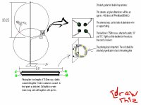
How to build one?...it's simple but the words escape me, I'll try, basically it's two 38.25" dia. loops with a slight overlap, both on the same plane, not perpendicular or anything...on one side where the loops overlap will be the feedpoint for both of them, it's actually diagonally polarized...ah heck...I couldn't make sense of this If I read it...I'll draw a pic....
Attachments
homer09 said:
i will disagree with this. i just cut my commercial cheapo dipole down to about 56". (i think there is an error in your calculations, 2.3m seems very wrong).
Yup, I forgot to divide by 2 to get a half-wave antenna.
- Status
- This old topic is closed. If you want to reopen this topic, contact a moderator using the "Report Post" button.
- Home
- General Interest
- Everything Else
- DIY FM antenna, can it be better than radioshack junk?