I do not expect this to make a significant difference at allFollow up query for the smps gurus..
Could I use PTC thermistor in line with the primary high side (+ rail) just after the bridge rectifier? I am thinking of a cheap short circuit protect that could act instantaneous when a fault happens inside the circuit. I am hesistant on using NTC because their resistance starts high during a cold start up. I am aware that the common practice is to install them right at one of the AC mains line entry but I've seen some circuit that had it connected after the bridge rectifier. Is this effective enough?
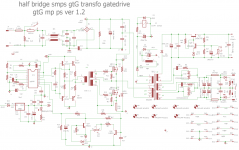
hi all , i have finished drawing schematic of my version of smps with pfc , it will be about 1,200 wts , i will use irfp 460 fets .
your views and comments are highly welcomed and appreciated.")
your views and comments are highly welcomed and appreciated.
Attachments
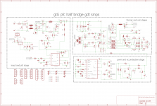
hi all i haven't found the ncp1653 so i skipped the pfc stage
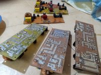
here are my projects for the low power and medium power
have fun all
here are my projects for the low power and medium power
have fun all
Attachments
-
gtG mp ps ver 1.2 to247 v2 diodes top components full.pdf53.8 KB · Views: 124
-
gtG mp ps ver 1.2 to247 v2 diodes.zip176.2 KB · Views: 128
-
gtG mp ps ver 1.2 to247 v2 diodes bottom pcb .pdf135 KB · Views: 115
-
gtG mp ps ver 1.2 to247 v2 diodes top pcb .pdf94 KB · Views: 107
-
gtG mp ps ver 1.2 to247 diodes schematic.pdf42.3 KB · Views: 119
-
gtG lp ps ver 1.2 to247 diodes top components.pdf148.7 KB · Views: 108
-
gtG lp ps ver 1.2 to247 diodes.zip176.2 KB · Views: 109
-
gtG lp ps ver 1.2 to247 diodes top pcb.pdf20.6 KB · Views: 103
-
gtG lp ps ver 1.2 to247 diodes bottom pcb.pdf64.5 KB · Views: 121
-
gtG lp ps ver 1.2 to247 diodes schematic.pdf40.9 KB · Views: 125
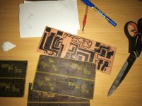
more photo of the build
Attachments
-
gtG lp ps ver 1.2 to247 diodes top components.pdf148.7 KB · Views: 129
-
 IMG_20200630_230759_434.jpg119.3 KB · Views: 159
 -
 IMG_20200630_230642_226.jpg76.9 KB · Views: 154
 -
 IMG_20200618_201208_885.jpg101.8 KB · Views: 121
 -
 IMG_20200617_005343_426.jpg89.4 KB · Views: 251
 -
 IMG_20200613_190156_304.jpg140.6 KB · Views: 241
 -
 IMG_20200613_190129_886.jpg133.8 KB · Views: 274
 -
 IMG_20200611_211735_153.jpg106.7 KB · Views: 292
hi all i haven't found the ncp1653 so i skipped the pfc stage
here are my projects for the low power and medium power
have fun all
Here on ebay I see a lot. https://www.ebay.com/sch/i.html?_from=R40&_trksid=m570.l1313&_nkw=ncp1653&_sacat=0
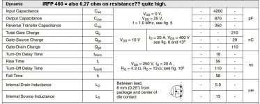
Nice schematics, doe you now that the IRFP460 has quite high on resistance?
Did use them on the circlotron because of in excahnge of higher on resistance a lower gate capacitance.
I was busy with resonance, but electronics is because of corona not so active on me now, have to help people, and mother of 89.
regards
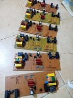
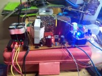
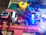
hi all , i have finally completed the smps based on silivio protection in the schematic on post #112 diysmps thanks silivio for sharing.
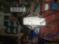
i used etd39 primary of 28 turns and secondary of 7 0 7 turns 3turns for auxilary.
i have a few questions 1 - the smps voltage slowly rises past 50volts without load but with load is stable at +/-35 vlts dc, why is that so?
2 - the protection at times false trigers and stays on and when there is no fault or overload , why is that so?
btw silivio thanks for the fan auto regulation section
Attachments
-
gtG lp ps ver 1.2 to247 diodes.zip176.2 KB · Views: 132
-
gtG lp ps ver 1.2 to247 diodes top components.pdf148.7 KB · Views: 134
-
gtG lp ps ver 1.2 to247 diodes schematic.pdf40.9 KB · Views: 136
-
 IMG_20200717_233150_597.jpg99.1 KB · Views: 125
 -
 IMG_20200717_233124_406.jpg123.4 KB · Views: 130
 -
 IMG_20200717_233117_297.jpg134.5 KB · Views: 142
Has this smps a feedback? if not then it can do 50 volts open, and 35 volts loaded, the slow ramping up of the voltage is maybe because of a to slow feedback error amp because of wrong parts.
The best way to go is a resonant, even without feedback it does quite stable voltages when it is adjusted the right way.
regards
The best way to go is a resonant, even without feedback it does quite stable voltages when it is adjusted the right way.
regards
With 2 n-channel power-MOSFETs you can do a 2-way sync-rectification for a single pos voltage. I do not know about any neg voltage solutions. But you can combine two identical pos circuits to a +- supply. Hope that helps.is synchronous rectifier able to be used at +/- 45volts? please draft a simple schematic.
Has this smps a feedback? if not then it can do 50 volts open, and 35 volts loaded, the slow ramping up of the voltage is maybe because of a to slow feedback error amp because of wrong parts.
The best way to go is a resonant, even without feedback it does quite stable voltages when it is adjusted the right way.
regards
thanks kees and bucks , but kindly provide a schematic to illustrate your explanations
I did only sim one because I was for a while to busy with family and corona, mother 89 has a lot of loneliness so needs to help.
here on forum there are thread,s about these smps resonant I believe.
It is quite a nice topology, low radiation and soft switching.
I have in the meantime different chips for building, it is needed to calculate right with software because it is critical.
regards
here on forum there are thread,s about these smps resonant I believe.
It is quite a nice topology, low radiation and soft switching.
I have in the meantime different chips for building, it is needed to calculate right with software because it is critical.
regards
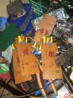
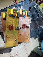
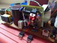
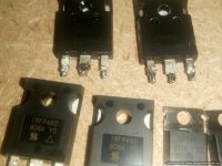
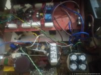
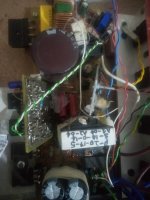
hello all , i have an issue the smps i made heats up irfp460 or 21n50c fets but if i use irf740 the heat is not present at the fets. when i put the bulb in series with smps and load a class ab with the bulb still in series the irfp460/21n50c they do heat insanely with little load and must be mounted on the sink. but irf740 are ok when smps has little or no load.
i tried changing the gate resistors from 22ohms to 47ohms but the heating was worse so i settled on the 4.7ohms it reduced the heating a little bit but did not eliminate the heating.
but when i used irf740 the smps worked well also with a little load to the amplifier the irf740s did not overheat but warmed without a heatsink.
the smps was
- gate drive transformer is ee16 trifilliar 12turns
- gate resistors 4.7ohms
- i tried with two etd39 formers
former 1 etd39 - primary turns 23turns, secondary turns 7t - 0 - 7t aux 2turns
former 2 etd39 - primary turns 42turns, secondary turns 14t - 0 - 14t aux 4turns
both formers behaved the same regarding the heating of the irfp460/21n50c
- i used a1020 and c2655 as buffers for the gdt and 1ohm resistors .(i had used 10 ohms resistor but results were similar with 1ohm)
note the same circuit i tried using igbt an year ago but it over heated abnormally a change of gate resistor didn't help in anyway .
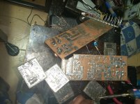
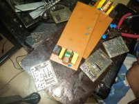
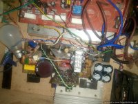
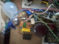
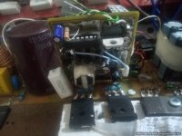
below are the pictures . kindly help out and any opinions are highly welcomed.
i tried changing the gate resistors from 22ohms to 47ohms but the heating was worse so i settled on the 4.7ohms it reduced the heating a little bit but did not eliminate the heating.
but when i used irf740 the smps worked well also with a little load to the amplifier the irf740s did not overheat but warmed without a heatsink.
the smps was
- gate drive transformer is ee16 trifilliar 12turns
- gate resistors 4.7ohms
- i tried with two etd39 formers
former 1 etd39 - primary turns 23turns, secondary turns 7t - 0 - 7t aux 2turns
former 2 etd39 - primary turns 42turns, secondary turns 14t - 0 - 14t aux 4turns
both formers behaved the same regarding the heating of the irfp460/21n50c
- i used a1020 and c2655 as buffers for the gdt and 1ohm resistors .(i had used 10 ohms resistor but results were similar with 1ohm)
note the same circuit i tried using igbt an year ago but it over heated abnormally a change of gate resistor didn't help in anyway .
below are the pictures . kindly help out and any opinions are highly welcomed.
Attachments
-
 IMG_20210517_140146_464-Optimized.jpg67.7 KB · Views: 143
 -
 IMG_20210517_173425_640-Optimized.jpg96.8 KB · Views: 88
 -
 IMG_20210517_140121_526-Optimized.jpg138.5 KB · Views: 84
 -
 IMG_20210517_135944_120-Optimized.jpg88.1 KB · Views: 84
 -
 IMG_20210517_135959_108-Optimized.jpg83.6 KB · Views: 178
 -
 IMG_20210517_135927_740.jpg452.5 KB · Views: 185
 -
 IMG_20210517_135935_786-Optimized.jpg92.6 KB · Views: 184
 -
 IMG_20210517_135927_740-Optimized.jpg57.8 KB · Views: 245
 -
 gtG lp ps ver 1.2 to247 diodes schematic.png50.7 KB · Views: 249
 -
gtG lp ps ver 1.2 to247 diodes schematic.pdf40.9 KB · Views: 118
I suspect your driver can't drive the mosfets without adjusting the dead time. I suspect you are seeing cross conduction when using the larger Fets. Adjust the duty cycle down a bit to provide enough dead time and I believe things should clean up for you. Search Google for sh3525 dead time control.
As you already mention, making the gate restance bigger, more heat get generated, this is simple to explain, the mosfet do switch slower and so deadtime needs longer.
Look always at the mosfet driver if it can drive high nC mosfets, use a gate resistance with a diode so mosfet switch off faster.
In mine eyes croscinduction appears to me the cause. so deadtime is not right, need more time. try to change the deadtime generator resistor change or put a pot x 2 afcourse there.
You have a gate transformer used to make a half bridge, did you make these or is that a ready made one? deadtime gereration can be affected.
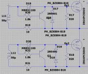
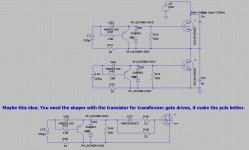
The need of a puls shaper after the transformer can help, for high power is this a idea to use. see on pics with the transistor and diodes.
The network of a diode with two resistors before the gate without the shaper circuit is used for deadtimes, but a transformer can have bad pulses and then is a transistor
shaping circuit a must.
regards
Look always at the mosfet driver if it can drive high nC mosfets, use a gate resistance with a diode so mosfet switch off faster.
In mine eyes croscinduction appears to me the cause. so deadtime is not right, need more time. try to change the deadtime generator resistor change or put a pot x 2 afcourse there.
You have a gate transformer used to make a half bridge, did you make these or is that a ready made one? deadtime gereration can be affected.
The need of a puls shaper after the transformer can help, for high power is this a idea to use. see on pics with the transistor and diodes.
The network of a diode with two resistors before the gate without the shaper circuit is used for deadtimes, but a transformer can have bad pulses and then is a transistor
shaping circuit a must.
regards
Attachments
Last edited:
i did wound the gdt former myself , ee16 trifilliar winding 12turns all primary and secondary twisted together ratio is 1:1 .
how comes the irf740 is not affected?, also a while back i used similar setup but with a class d amp and the irfp460 . survived and did a good job . but now with a class ab amp at btl mode the irfp460 heat up fast. but the ir740 are ok although up to 5volts per rail voltage drop when volume is high.
how comes the irf740 is not affected?, also a while back i used similar setup but with a class d amp and the irfp460 . survived and did a good job . but now with a class ab amp at btl mode the irfp460 heat up fast. but the ir740 are ok although up to 5volts per rail voltage drop when volume is high.
Maybe because of this, the nC or gate capacitances arde different.
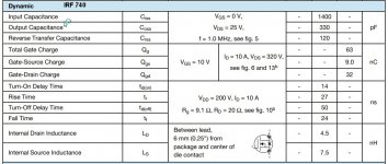
The IRF 740 has 0.55 ohm on resistance, and the IRF 460 has 0.27 ohm on resistance. Because you say the irfp 740 does a lot better do point to the input capacitance, for 740 quite low, but the irf 460 is quite high, see the spec in pics. it is 4200 pF against 63 pF.
You need to use mossfets for smps have low on resistance and low nC otherwise use a puls chaper like I let see with transistor and diodes, these are used with transformer drivers, making a transformer is quite precise, you need good pulses otherwise deadtime has to be bigger making more losses.
How to Select a MOSFET – Switch Mode Power Supply - Power management - Technical articles - TI E2E support forums
If you want paralell mosfets a higher on resistance is maybe a good factor for paralelling.
Dit you have watch the puls from the transformer with a scope? and also watch the deadtimes.
Attachments
Last edited:
- Home
- Amplifiers
- Power Supplies
- Offline full-bridge SMPS… need help