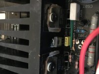
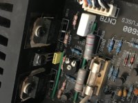
Hi thanks for quick reply I’ve found loads of Cambridge schematics but as you say nothing on the early on. Will check the thread thanks. Here are photos of q611 and q311 which is the offending one. Unscrewed from heatshink but nothing on the back either bit of a mystery! I have emailed Mike Creek this am so hoping I might get something back. If you do have the time to check yours that would be great cheers Antony ps can’t seem to find photo upload function hope to post them shortly
A1
Hi new to this posting stuff not sure if my message was posted! Sorry if this is twice. It’s q611 and q331 ( behind yellow film cap)which is the faulty one even detached from heatsink and no markings there either. Have attached photos. Would be great if you have the time to check yours. I have emailed Mike Creek hoping he can help. Started on reading post some interesting stuff but nothing about the driver transistor cheers Antony
Hi new to this posting stuff not sure if my message was posted! Sorry if this is twice. It’s q611 and q331 ( behind yellow film cap)which is the faulty one even detached from heatsink and no markings there either. Have attached photos. Would be great if you have the time to check yours. I have emailed Mike Creek hoping he can help. Started on reading post some interesting stuff but nothing about the driver transistor cheers Antony
Attachments
That's a pity but coincidentally, only a few days ago I bought a pair of new (2020 dated) Philips 70W B22 halogen bulbs, available here on the premise that lighting dimmers don't work with LEDs and the power generation (carbon) cost here is now borne by the consumer who generally has solar power arrays and battery storage to absorb the bulk of domestic power generation needs. Excess is returned to the grid for a metered rebate.To Ian Finch, will have to stick to the 60W one been to 3 stores and only LED ones available......
In any case, Oven makers in the UK and Europe supply miniature wire pin type 230V halogen bulbs up to 60W (Osram - RS components) 40W(Smeg) or MES types (dealsan) Theyr'e not cheap and you need to be careful to prevent any contact with the extremely hot bulb in makeshift DBT arrangements. Use a proper heat resistant connector for the wire pins such as found in wrecked automotive headlamps and some old 12V-24V downlights. Keep them well out of reach, as I've burnt myself more than once whilst peering into dead amplifiers.
One or two of those larger bulbs, sharing power as the need arises, should be fine for many small to medium power amplifiers.
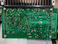
PCB side
Hi, in case someone would be interested, there is picture for PCB side...
I'm fighting with mine A3i having loud cracks appearing in speaker with turned on amplifier. When heats-up cracking still present but only time to time... like random loud pops only in R channel.
Q8/Q10/Q108/Q110 replaced with BD139/BD140.
LEDs are still not changed, waiting for parts, but all 4 glowing evenly, idle current for outputs adjustable and set correctly, only issue is DC on R ch is above/about threshold for protection, sometimes it triggers, then releases. DC in R channel is around 0.5v and it varies.
After repairing of Yamaha and Marantz amplifiers I found repair of Cambridge Audio A31 a true nightmare! What a mess in layout! Seems that it was used "auto-placement" for PCB feature in CAD.
Repairing the A3i requires a systematic approach.
Once you have replaced the 4 green LEDs and ensured they are raised from the board also replace the FET Q107 ZVP3306, I would also do the same for the left channel.
The FET(s) is the most common cause for the noise your describing.
DC offset will be caused by the transistor(s) in the input stage of the Amplifier.
Typically Q101 Q102, as the transistors are inexpensive I always block change them out and replace not only the above but also Q105 / Q106 and Q103 / Q104 and do the same for the left channel.
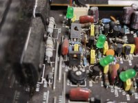
As your photo has confirmed there are multiple dry solder joints on the board the joints are dull and cracks can be seen.
Reflow them to ensure all the solder joints are good.
As the Amplifier is old and no doubt seen long service I would also replace the speaker protection relay as the contacts will be worn and oxidized.
Once the above has been done you can then set to Bias to 12 millivolts for each channel , don't forget to clean the input selection switch and control potentiometers with a good quality switch cleaner.
Once you have replaced the 4 green LEDs and ensured they are raised from the board also replace the FET Q107 ZVP3306, I would also do the same for the left channel.
The FET(s) is the most common cause for the noise your describing.
DC offset will be caused by the transistor(s) in the input stage of the Amplifier.
Typically Q101 Q102, as the transistors are inexpensive I always block change them out and replace not only the above but also Q105 / Q106 and Q103 / Q104 and do the same for the left channel.
As your photo has confirmed there are multiple dry solder joints on the board the joints are dull and cracks can be seen.
Reflow them to ensure all the solder joints are good.
As the Amplifier is old and no doubt seen long service I would also replace the speaker protection relay as the contacts will be worn and oxidized.
Once the above has been done you can then set to Bias to 12 millivolts for each channel , don't forget to clean the input selection switch and control potentiometers with a good quality switch cleaner.
I repaired a load of this A3i amps and they can be a headache if they start playing up.
Right now ( is on hold until better date) I have one that is driving me mad.
It started with a common failure (led out) and after replacement ( replaced all 4 with matched ones) and all transistors checked it powers up with all 4 leds on but led101 is brighter than the others and can't figure out why.
(tests done with inline bulb protection)
Any ideas ?
Its my favorite Cambridge Audio "A" series amp and I had all of then apart from the A4 but I know the amp has the same amp board like the A300/A500, A5 and others but so can't be that different.
You are correct, of course. I misread 34 for 24 on the murky image I strained to see. I had downloaded a copy of the Cambridge Audio A3i service manual front page and alignment procedure attached to what looks like 3 pages of Creek Audio's schematics showing 34V, not 24V rails. Funny enough, on a second download, it came up clear and legible. Anyways, good luck on the search.
Regarding recapping, wondering how influence on sound is split for different amp stages using el.caps?
So I read Alex mentioned that VAS PS caps are most important to change to some good quality (C216, C217) and he used Panasonic FC with good result.
Is it the only one place where is justified re-capping, as long other caps are fine?
Does anyone have rough idea of how much in percentage caps affecting sound, e.g. something in following way, numbers are out of the ceiling:
VAS PS (470uF/63v) - 60%
Main PS (10.000uF/50v) - 10%
NFB (100uF/35v)- 10%
Input (10uF/63v) - 20%
Usually I'm following principle "not to repair what is not broken", and that applicable to capacitors, so I would never change anything that works fine, except I could see huge benefit of changing some "cheap crap" (despite it's working), in one or few amp stages knowing that this change would improve amplifier sound dramatically and will put it one or two levels up in amp ranking.
Happy to report that amplifier is finally fixed.
For pops and cracks in R-ch was guilty resistor R107, which was faulty in odd way, it measures 47k instead of 39k (based on colour coding on it).
Supposedly it was cracked or something inside and while heating it changes resistance of completely losing resistance, therefore pops and cracks happens in sound.
After replacing it, sound was all right.
Still wanted to sort out issue that R-ch initial DC offset in output was bigger that threshold for protection, and relay triggered only after some wait time.
From cold DC offset started from 1.9V, and with heating it lowers till accepted.
And from cold all current was taking Q113 and together with heating, Q114 takes current bit by bit, but never it was equal for both.
For fighting this issue it I have replaced all LEDs, all transistors (except Sankens), still the same. All transistors selected measured for matching. Spend all Saturday - no result, gave up.
Now, today I have read few pages back till 'Audio Service' post #330 - "...Clean the top of the board before refitting the new devices..." and after I have cleared PCB top layer with scrubbing 99% alcohol - magic happened! I got DC offset 1mV and both outputs shares current equally straight from the cold start.
Thank you 'Audio Service' for valuable advice!
Before this case I never paid attention for cleaning. But with this amplifier I hade to clean both sides of PCB because on solder side it was released from factory not washed at all, all surface covered by sticky soldering halfly dried fluid. And on some areas soldering liquid got into PCB face side around some parts. btw had to re-solder all soldering points as almost all were deteriorated sometimes with visible splitting in between soldering point. Only need to use magnifying glass to spot it.
Fot the same replaced all el.caps with Panasonic new FM series.
Very happy with the result. Sound is beautifully pleasant - strong and calming in the same time. No usual transistor sharpness on high freq. I must say I enjoy it in the same way as I enjoy my valve amps.
p.s. I have replaced FETs as well even if sound was the same good as before replacement. The only oddity is that when I measure new FET with "smart ESR tester" it shows that FET is inserted. But de-soldered FET shows only as diode between legs 1-3.
Does it mean that FET was faulty? Why then amplifier sounded right then?
p.p.s still got feeling that with this amp is still something wrong, not as supposed to be as it produces too much heat I was observed in any of my other amplifiers, more heat is coming from PCB, not from output heatsink. Now I set conservatively low idle of 10mV across 0.22 res. If nothing bad happens in few weeks, I will add a bit more.
I often had this good-sounding amplifier (unfortunately with very bad reliability) to be repaired (at least 20 devices from this model).
However, one must note that one cannot actually speak of a usual repair resp. troubleshooting work.
An extensive revision is always necessary - a list was once posted somewhere, what everything had to be done in order to get the reliability to a level, as one is used to from good designs.
The most significant deficiencies are the kind of workmanship and too many thermal stress at several places around the front-end of power amp section.
Additional there was to observe a very annoying mechanical hum of the R-core transformer, which annoys many users.
How could it be, that a completely mature and therefore unreliable product comes onto the market?
I don't want to know how much time was wasted because hi-fi dealers somehow had to justify themselves to their customers for the fact that they turned the customer into "junk" without their own intention.
As a customer (and non-specialist), I would have definitely blamed my dealer from my local hifi shop for it, although in real life the manufacturer (in this case Cambridge Audio) is responsible for such a disaster.
Last edited:
The R-Core probably didnt hum like that when these amps were released, and switch mode supplies were relatively uncommon. Now they are everywhere and the distorted mains waveform with DC offset that is now common is what pisses the R-Core off.
As Alex said, he designed the amp for a lower supply voltage. Managers playing at being engineers are the cause of the unreliability.
As Alex said, he designed the amp for a lower supply voltage. Managers playing at being engineers are the cause of the unreliability.
- Home
- Amplifiers
- Solid State
- Cambridge Audio A3i repairs and mods