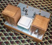
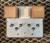
My dad turns 74 this week... I built this for him
Total cost about 300$ CAD.
~10WPC 14Hz-50kHz
12SN7 front end, 6F12P VA/PI, 6P43P output, triode connected, Eff Ra-a ~3k@8R using interleaved Triad VPT12-2080 as the OPT.
I love it, can you please explain how you used a couple of power transformer like the VPT12-2080 as OPT? ....all the best
kodabmx,
That amp looks great!
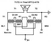
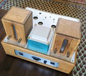
It looks like you used 2 toroids per channel.
Did the toroids have dual primaries, and did you connect them so as to have a "center tap"?
And then parallel 2 toroids dual primaries; and parallel the 2 secondaries?
Or, did you wire one plate to one toroid primary; and the other plate to the other toroid primary, but in opposite phase (plate to B+) versus the first toroid?
And then parallel the toroid secondaries in opposite phase to make it all work?
That amp looks great!
It looks like you used 2 toroids per channel.
Did the toroids have dual primaries, and did you connect them so as to have a "center tap"?
And then parallel 2 toroids dual primaries; and parallel the 2 secondaries?
Or, did you wire one plate to one toroid primary; and the other plate to the other toroid primary, but in opposite phase (plate to B+) versus the first toroid?
And then parallel the toroid secondaries in opposite phase to make it all work?
Last edited:
Thanks.
Yup. Dual pri, dual sec.
I interleaved the primaries and connected the secondaries in series for about 2k2-6R
Nice, How is the sound? Did you got a chance to compare this using EI core OPT?
Thanks,
Bibin
This setup consistently outperforms any of the EI transformers I've used. Much better LF response, too.
And of course 4 of those coils costs less than one standard EI OPT of the same VA rating...
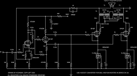
Here's the complete schematic minus PSU for anyone who's interested.
And of course 4 of those coils costs less than one standard EI OPT of the same VA rating...
Here's the complete schematic minus PSU for anyone who's interested.
Attachments
Last edited:
This setup consistently outperforms any of the EI transformers I've used. Much better LF response, too.
And of course 4 of those coils costs less than one standard EI OPT of the same VA rating...
Here's the complete schematic minus PSU for anyone who's interested.
Great, thank you for sharing the schematic. Is there any possibility for SE OPT using similar arrangement?
Thanks,
Bibin
Since there is no gap, you would need to use one of the windings to counteract the DC flowing.
You could use a big resistor to load one side of the primary (or build a PP amp and ground one power tubes' grid), or you could use one of the secondaries, and say a 12V PSU with adjustable current to get the nulling in the core. Otherwise, this is really only suited to push pull.
You could use a big resistor to load one side of the primary (or build a PP amp and ground one power tubes' grid), or you could use one of the secondaries, and say a 12V PSU with adjustable current to get the nulling in the core. Otherwise, this is really only suited to push pull.
Work of art!My Baby Huey PP EL84
Since there is no gap, you would need to use one of the windings to counteract the DC flowing.
You could use a big resistor to load one side of the primary (or build a PP amp and ground one power tubes' grid), or you could use one of the secondaries, and say a 12V PSU with adjustable current to get the nulling in the core. Otherwise, this is really only suited to push pull.
Thank you for the details, better to try the same PP then. Can you share the details of PSU and boost converter?
Looks nice...My Baby Huey PP EL84
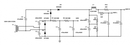
Thank you for the details, better to try the same PP then. Can you share the details of PSU and boost converter?
This is the basic idea using a quadrupler instead of the boost converter... Also it's mismarked... 560V is more like 640V...
Search eBay for "12V 280V" and you'll find the DC board I usually use though.
Attachments
I'm pretty sure I've seen those covers in one of those small Swedish storesMy Baby Huey PP EL84
")
Great idea of routing the corners though.
Nice amps both. Are they those Ikea cheese boxes or whatever again Bas? like the colour scheme too.
Koba, what's your experience with Kemet caps? I've alus thought of them as being a bit crap, yon green puppet frog keeps popping into my head too when I see them on Farnell. This is based completely on prejudice though, it's easy to get a bit sniffy about certain makes of parts if your not carefull.
Like the on/off sw, swanky and must have a go at the way you do your OPT's, anything that saves a few bob in that dept has to be worth a try.
Andy.
Thanks Dave!Another nice amp Bas!!
Correct. Ikea Estetisk.'m pretty sure I've seen those covers in one of those small Swedish stores
Thanks. Those are the Ikea pencil cases indeed.Nice amps both. Are they those Ikea cheese boxes or whatever again Bas? like the colour scheme too.
This is the basic idea using a quadrupler instead of the boost converter... Also it's mismarked... 560V is more like 640V...
Search eBay for "12V 280V" and you'll find the DC board I usually use though.
Thank for the PSU details
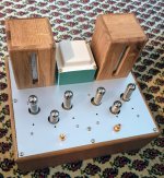
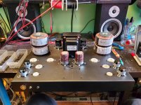
Starting another build... Not bad for a few hours work... It was a blank chassis this morning
Looks interesting, and expecting more photos of your build.
- Home
- Amplifiers
- Tubes / Valves
- Photo Gallery