Hey LATB,
You can mount up 2 of these heatsinks to form a 'heatsink tunnel' and blow a breeze down them for cooling - many silent computer fans come with a temp control too.
You could also think about using a Cap Multiplier power supply too - a big improvement in the sound for about a 2 - 3 volt rail loss. There's a couple of these projects here on Diya ...
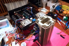
A guess at your heatsinks thermal efficiency.
if you're getting to 50*C with a bias at 0.85A (note: standing vertically in free air) and assuming your room temp is about 25*C, then power into the heatsink is 2 x 26 (+ and - 26v rails) x 0.85A = 48watts. Temp rise because of this extra power is 50 - 25 = 25*C rise. So "efficiency" is 25/48 = 0.52 *C/W.
I've used these sinks over the years and they're actually closer to about double that when enclosed (1*C/W) so if you're going to blow some air over them when they're operating at say, 1.8A and the similar 26V rails, then you're pumping about 90 odd watts into them (per heatsink) and this would require something like 5 - 10 cu feet air/minute thru the tunnel, a slow breeze and virtually totally silent.
The temp control is because my calculations are just a guesstimate but would be somewhere "in the ballpark", as they say
A guess at your heatsinks thermal efficiency.
if you're getting to 50*C with a bias at 0.85A (note: standing vertically in free air) and assuming your room temp is about 25*C, then power into the heatsink is 2 x 26 (+ and - 26v rails) x 0.85A = 48watts. Temp rise because of this extra power is 50 - 25 = 25*C rise. So "efficiency" is 25/48 = 0.52 *C/W.
I've used these sinks over the years and they're actually closer to about double that when enclosed (1*C/W) so if you're going to blow some air over them when they're operating at say, 1.8A and the similar 26V rails, then you're pumping about 90 odd watts into them (per heatsink) and this would require something like 5 - 10 cu feet air/minute thru the tunnel, a slow breeze and virtually totally silent.
The temp control is because my calculations are just a guesstimate but would be somewhere "in the ballpark", as they say
Thanks for the quick calculation! You're right -- I noticed that even a faint breeze from this little fan I have to avoid soldering fumes made a huge difference.
The amp was running for a few hours during the day, and I had it in a tunnel configuration like shown, as you suggest. I made sure it could ventilate from below creating a bit of a chimney effect, which already helped a little, but it was not enough.
I've now soldered the other channel and will try it with some a slow running fan and report back.
Thanks for all the feedback!
BTW, I learned something else today: I had no idea that 10,000uF caps, > 25 year old, would keep their charge for months?? I mean, all eight of them, for several months! Surprise! I hope everyone else is safe...
Cheers, LATB
Attachments
Hey LATB,
[...]You could also think about using a Cap Multiplier power supply too - a big improvement in the sound for about a 2 - 3 volt rail loss. There's a couple of these projects here on Diya ...
I'll read up on the Cap Multiplier discussions in some of the other threads. The 2-3 Volt drop would still produce the equivalent of ~10 Watt heat (assuming I manage to get to a ~1.85A bias current).
BTW -- I'm still worried about my precious LSJ74s (were these guys always that expensive?) with their breakdown V_GDS of 25V. When I switch on, while the Bias slowly comes up, the rails go from 30V down to eventually 26V. So I left them out, for the moment.
So, I'm considering resistive voltage dividers as @schiirrn proposed. Or to just go all in with Cap multipliers.
--LATB
You could just use a bigger value resistor in the C-R-C to reduce your rails another volt but the cap multiplier will stop this initial higher voltage as it actually produces a slow voltage rise in the rails to the final value.
If you use 1.8A for each channel = 3.6A together and 2.5v drop = 9w total - so yes, this has to be 'sunk' too.
However, IMO here, it's better to use separate Cap Multipliers for each channel and this isn't as onerous as you'd think as you do have 2 transformers, use 2 separate bridges (Schottky, if possible - ideally, use Shindengen ones) and just use a single 10,000uF ripple cap before each cap multiplier (Cap Mx) for each rail and mount the main power fet and it's pcb/other components on the same heatsink.
This setup is known as 'dual mono' and allows for 'simpler' ground/0v connection.
There has been much discussion about the position of the power supply ground point(s) but broadly speaking, either continue to use the mid point between the ripple caps as the 0 volt point for each channel and a 'ground lift' CL-60 back to the chassis earth point or move the new central ground point onto the mid point of each channel's Cap-Mx pair and connect this to the chassis earth via the CL-60 and then link a wire back to the ripple capacitors - this way works well for me, but other people have success with different grounding systems.
I use a Mark Johnson version (known as "Mark Johnson/Gtose" in the GB section) - It's a pretty simple circuit but works like a charm.
"X" also has a more sophisticated version with the fet rectifiers instead of the normal bridge and it too only drops about 2.5 volts - the "Smooth as Butta" one.
Then the very simple "juma" version uses the IRFP fets and drops about 4.5v across the power fet - this is the same as shown in some of the First Watt amplifier power supply circuits - it too works quite well
There are many others as this type of power filter has been around for a long time.
I'm a bit like you and hate the idea of burning out one of those j74 fets - I stlll have some of the Toshiba ones and they're supposedly a bit more robust but not willing to risk frying them - I don't know if you've tied the 2 input jfets together with a 'mini' heatsink - just a clipon one will help.
From previous post, photo shows your heatsinks are much better/more efficient than the ones we had out here so maybe revise the thermal rating back up a bit higher to about 0.7*C/w.
One thing I did learn was to allow a bit of space between the fan and the ends of the heatsinks to stop air flow noise - about 20mm (3/4" seemed to work okay
Also, I think nearly all the modern fans come with soft mounting washers - they're a bit hard to find as a separate item - I thought the ones with illuminated blades were a gimmick but they actually show any dirt buildup so indicate a needed clean - sometimes dirty fans start to vibrate and create noise too.
Yes, I've had some nasty experiences from old stock higher voltage caps too! most unpleasant.
Hopefully, you're (and anyone reading this natter!) are avoiding this nasty virus going around -we've adopted the Vitamin C, D, Quercitin, etc preventative measures plus we're on extensive house isolation - it's showing promise but is a total disaster to the economy.
Yeah, I sourced quite a few of those fancy Siemens Sikorel caps awhile back - they're like the size of beer cans in comparison to the current ones but still perform extremely well even after a lot of years - those ones in the photo look like Panasonics and they also age quite well so hang onto them.
Adding a fancy power supply doesn't necessarily sound better to everyone as the so-called 'upmarket' version has a slightly different sound and some folks prefer the 'basic supply sound' so I wouldn't go rushing to build Cap multipliers in your power supply until your amp has been up and running for awhile and see if you want to experiment with the unit, or not.
Remember, better sound to some people may not actually sound better to you at all and do include my opinions in this too.
I listen to headphones a bit and am attracted to all the "razzamatazz" that comes with modding things, power supplies included - but I've also found that not always do technical improvements translate to better sound when you settle down and have a longer listen!
thanks, very helpful pointers, am reading and learning a lot (why, again, did I buy all these caps?)")
But then: this F6 is dead quiet -- even with all these long wires hanging around.
Yesss Tombstone quiet ..V nice.
Many here build constantly.. fiddling about is their hobby.
Some build for listening use.
If a user don't waste time trying to 'gild the lily'
I want to build the F6, although I'm not very good in DIY I wanna try it with one friend (who is good in it) - is there a website / online-shop where I can buy all the kit. Apart from the hours of work, what would be the cost of all the parts on the BOM? I'm living in Austria/Germany, so I would have to calculate Europan taxes as well.
Cheers! Martin
Cheers! Martin
I want to build the F6, although I'm not very good in DIY I wanna try it with one friend (who is good in it) - is there a website / online-shop where I can buy all the kit. Apart from the hours of work, what would be the cost of all the parts on the BOM? I'm living in Austria/Germany, so I would have to calculate Europan taxes as well.
Cheers! Martin
Start here...
F6 Parts Kit – diyAudio Store
Choose option with all the parts minus the JFETs.
Then go ... here...
Linear Systems Matched JFETs – diyAudio Store
Choose a matched Quad.
Then go ... here...
Deluxe – diyAudio Store
and pick your favorite ... then go here...
Chassis Accessories – diyAudio Store
and get a back panel parts kit...
Go here...
Universal Power Supply – diyAudio Store
and get one of those... or two if you want dual mono.
Add ~$150 USD in parts for the PSU and other stuff like wire and other incidentals.
That will get you 95% of the way there with a ballpark cost. Your friend that is experienced with DIY can help you out with the 1,000s of other optional ways to do it and maybe save some money too. What I've outlined has been done quite a number of times with successful results. It should be close enough to help you decide if you want to take on the project and just how much of it you want to do yourself or buy "kit form".
I'm sure others will chime in with many other alternatives. It's inevitable that you'll forget to order something...
I hope you have a ball building your amp!

Hi Martin,
ItsAllInMyHead has given you lots of good suggestions.
Since you're in the EU, for power transformers I recommend Toroidy:
Transformatory toroidalne - Producent transformatorow Toroidy.pl
Cheers,
Dennis
ItsAllInMyHead has given you lots of good suggestions.
Since you're in the EU, for power transformers I recommend Toroidy:
Transformatory toroidalne - Producent transformatorow Toroidy.pl
Cheers,
Dennis
Yes, what he said.
However the kit with the fuller set of parts has been sold out for a while. The smaller kit with boards and Jensen transformers is still a good option. The output Mosfets are easy because they don’t really need to be matched. Resistors and capacitors are also easy. Use Nichicon FG or KW series for the 1000 uF pieces.
Go dual mono if you can.
After years of buying super expensive hifi gear from people, who just want so sell and not "help" to get a better audio experience... this is just great. I've been in contact over the last weeks with a lot of guys from DIY on different platforms and this is just great.
Thank you itsallinyourhead for your information. Fantastic, that was what I was looking for... thanks also to the others.
The amp of course should match with the speakers: I'm still not sure which one to build: I'm quite sure I will try some speakers from Troels - the pre-selection has been made:
Ekta-25
CNO-25-mkII
SBA-16-MTM
Faital-3WC
SBA-941
http://www.troelsgravesen.dk/SEAS-3-Way-Classic-mkII.htm
Which speaker would definitely NOT match with the F6? Any other input which could be a good match. (Sorry for being OT here, I'll come back to the F6 after this...)
Regards,
Martin
Daughter Boards?
Humm. I’m just about to wire everything up. But I have all these DB’s, M2x and Yarra, waiting for a home. I haven’t built the M2x yet, the F6 sort of cut in line. Had all the goodies for it. Now would be the time to rig this to use the DBs.
Tungsten, you built a mod version of the Austin. Was that to adapt it to the F6, or your FAB self tinkering with it. So really the question is, will the M2x and Yarra DBs work with the F6 without mods?
My Psu output is just shy of 26v both rails. So I’m not really running into an issue there.
My F6 power rails were +/– 26V, but the standard F6 input stage doesn't have any source degeneration on the JFets. I used a variation of the Austin input stage that is included with the M2x. The Austin IPS is a version of what is commonly known as a diamond buffer. It can be readily adapted to drive the F6 in place of those two lonely JFets. I built it on a veroboard like so:
Humm. I’m just about to wire everything up. But I have all these DB’s, M2x and Yarra, waiting for a home. I haven’t built the M2x yet, the F6 sort of cut in line. Had all the goodies for it. Now would be the time to rig this to use the DBs.
Tungsten, you built a mod version of the Austin. Was that to adapt it to the F6, or your FAB self tinkering with it. So really the question is, will the M2x and Yarra DBs work with the F6 without mods?
My Psu output is just shy of 26v both rails. So I’m not really running into an issue there.
Mark Johnson has valid concerns for the longevity of the ZTX output transistors used in the Austin IPS for rail voltages much over 24V. Those parts do perform quite well, given the recommended PSU for the M2x. They are also chosen to fit onto a space constrained PCB. Replacing them with the larger Toshiba devices was a simple engineering decision to allow the input stage to run 24/7 in my amp without having to worry about device longevity.
Removing the R8 + C4 network used to control minority carrier injection during high speed transients, replacing that with 10 Ohm base resistors in front of Q5 and Q6, and reducing R9 & R10 to 10 Ohms; that was just me being my FAB self.
I haven't done the analysis on the Yara DBs to check for hgher voltage. I suspect a couple of the designs will work fine, maybe with some resistor value tweaks. I happen to have some of those as well, but haven't built my Yara yet. I did originally intend to try the Melbourne boards in my M2x, either tweaked for lower gain, or running at full 20 dB gain with the Edcor transformer bypassed. Maybe will try that sometime if I run out of other things to do. FAB self wants to know.
...The output Mosfets are easy because they don’t really need to be matched. ...
Go dual mono if you can.
Thats correct if you build the unmodified diyaudio.com version which has no AC degeneration and has dominantly 3rd harmonic distortion. If you want dominant second with negative phase and use AC degeneration as described in Nelson Pass talk at BAF, you better use a matched quad or you have a potentiometer tapping the lower source resistor (as done in the production units) and adjust it with a spectrum analyzer and a dual trace scope.
Matched quads of Mosfets are often sold for Aleph builds and this is the easiest way if you want to try the 2nd harmonic dominant variant.
@lukrez / Martin -
I am not familiar with those speakers. I did a quick scan of the models. With (I think) the exception of one, they're all 4 ohm and around 91dB / 2W (2.8V) 1m. You can back out power requirements at your listening levels at your general listening distance. Better yet, if you haven't already, if anyone on the speaker forums or here has experience with one of the combinations to share, it could point you in the right direction. My guess is that the F6 would be excellent at "normal" listening levels in a "normal" room with any of those speakers, but those that have tried the combination will know much better. There were a few comments re: using some of the models with lower wattage tube amps. So, again... you'll likely be just fine.
I also happen to have an iFi Micro BL - Yes, it will work. I haven't tried using it as a pre-amplifier yet. I've only used it for HPs. Therefore, no judgement one way or the other on my part. Battery power should keep it very quiet.
However, depending on how much of your budget the F6 and speakers use up... while you're shipping things... and if you have the space... you could consider a dedicated pre-amp. There are a great number of options both DIY and retail. If not, you can always build one later after you've finished your F6 and have become addicted to DIY
^ This is good advice.
I have been using different Mosfets in my F6, the FQH44N10 instead of the IRFP240. I selected four from a lot without bothering to match them. Measurements done later with my distortion analyzer indicated low distortion, and a relatively even mix of H2 and H3, perhaps more H3. I probably got lucky with my choice of devices, so the safe thing to do would be to test and look for relatively close matches. There has been some discussion about whether devices need to be matched within a channel, or per device location across the two channels. So there is a decision to make. I decided not to worry, and that would also be my recommendation for a novice builder.
Working with suggestions by 2 picoDumbs, I later modified my amp to add AC degeneration to the upper Mosfet in each channel. That increased the relative amount of H2, and the overall THD. I liked the sound, so I kept it that way.
Last edited:
- Home
- Amplifiers
- Pass Labs
- F6 Illustrated Build Guide