Hi Codyt and McQuaide
I have followed with great interest in your elimination of Pearl2 output caps.
Is this simply a case of eliminating c13 with a wire and bypassing R14 with a lytic to achieve zero DC?
I would like to try this too.
tia
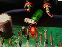
I put a silmic cap between R14 and ground and verified 0VDC at the output. Then put a jumper on C13 and removed C8.
I put a silmic cap between R14 and ground and verified 0VDC at the output. Then put a jumper on C13 and removed C8.
Same. I also added a .1mf bypass to the 220mf electrolytic, but the benefit of that is questionable. I’ll upload a picture in a bit.
Thanks a lot, McQuaide and Codyt.
It is quite clear about c13 and c8
So add a 220 cap between r14 and ground?
It is not clear on your images, but I could just lift the board edge side leg of R14 and add the cap there would be my simplest option.
It is quite clear about c13 and c8
So add a 220 cap between r14 and ground?
It is not clear on your images, but I could just lift the board edge side leg of R14 and add the cap there would be my simplest option.
I put a silmic cap between R14 and ground and verified 0VDC at the output. Then put a jumper on C13 and removed C8.
Last edited:
Thanks a lot, McQuaide and Codyt.
It is quite clear about c13 and c8
So add a 220 cap between r14 and ground?
It is not clear on your images, but I could just lift the board edge side leg of R14 and add the cap there would be my simplest option.
Yep, that all I did. It’s pretty straightforward
Thanks a lot, McQuaide and Codyt.
It is quite clear about c13 and c8
So add a 220 cap between r14 and ground?
It is not clear on your images, but I could just lift the board edge side leg of R14 and add the cap there would be my simplest option.
I put in a 47uF, I don't think the value is critical.
Thanks a lot, McQuaide and Codyt.
It is quite clear about c13 and c8
So add a 220 cap between r14 and ground?
It is not clear on your images, but I could just lift the board edge side leg of R14 and add the cap there would be my simplest option.
Here’s a pic
Attachments
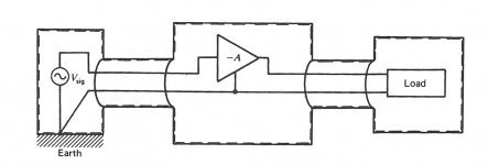
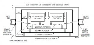
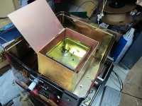
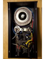
The first image is from Morrison's "Ground and Shielding Techniques in Instrumentation", the second from Linear Tech (ADI) AN-159 "Measuring 2nV/RtHz Noise", third the shielded box I use for noise measurements -- I can measure down to ~500pV/RtHz
Attachments
Last edited:
Well I finished everything up and plugged everything together, fired it up and no sound.
I am running from the TT RCA’s to the Pearl 2 inputs. Pearl 2 output to the B1 input. B1 output to the RCS’s. I did away with the B1 selector switch so I have a jumper on R1/L1 to the middle pad. I did not remove R101 or R201 on the B1 as I do not believe it is necessary to do so.
I will have to look into a bit later and see what is going on.
I know I have 30+, 30- going to both Pearl boards and 0 at the checking offset (I believe) test point. LED’s are on, on all three boards.
Well I finished everything up and plugged everything together, fired it up and no sound.
I am running from the TT RCA’s to the Pearl 2 inputs. Pearl 2 output to the B1 input. B1 output to the RCS’s. I did away with the B1 selector switch so I have a jumper on R1/L1 to the middle pad. I did not remove R101 or R201 on the B1 as I do not believe it is necessary to do so.
I will have to look into a bit later and see what is going on.
I know I have 30+, 30- going to both Pearl boards and 0 at the checking offset (I believe) test point. LED’s are on, on all three boards.
Here are some voltages to check.
Attachments
Sounds like a flashback to my early 1970s days!

Hmmmm, I don't remember what it sounded like, but mine and another member or two that used certain MC, mine an SAE had a mismatch problem. A simple Zobel on the input resolved the problem. 6L6 came up with the "cure" for it as I recall.
Russellc
Russellc - I didn't come up with the cure, I just picked up the phone and asked Wayne... Some High-Output MC cartridges have a lot of turns on the motor and their inductance can start to ring looking into the loading resistor. The input Zoble fixes that if needed, but the couple of people who have have that problem have had the exact same cartridge!
exojam - please post some photos. (Well-lit, in-focus, you know the drill... )
Some High-Output MC cartridges have a lot of turns on the motor and their inductance can start to ring looking into the loading resistor. The input Zoble fixes that if needed, but the couple of people who have have that problem have had the exact same cartridge!exojam - please post some photos. (Well-lit, in-focus, you know the drill...
)I’m going to tackle this build next. Does anyone know where to get the power supply board since Chipamp’s website is no longer available?
You can probably find a nice one on eBay. I’ve heard good things about Tubecad/Glassware boards too: Low-Voltage Power Supplies
I’m going to tackle this build next. Does anyone know where to get the power supply board since Chipamp’s website is no longer available?
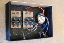
With a little help from my hot glue gun, I found the power supply published by Wayne to be really easy to build P2P.
Attachments
I’m going to tackle this build next. Does anyone know where to get the power supply board since Chipamp’s website is no longer available?
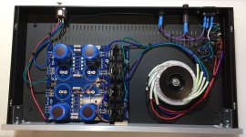
You can also use the DIYaudio store PSU board to build Wayne's supply. I spent the extra $1 each to add heat sinks to the fast diodes but they probably aren't necessary. Safety ground isolation components are on a terminal strip next to the IEC inlet.
Attachments
- Home
- Amplifiers
- Pass Labs
- Building a Pearl 2