Hi,
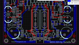
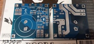
Because I was curious to build this headphone amplifier, I made a PCB (second) variant more compact.
The first one was 12 x 12 cm and had some mistakes. It is not an original version but adapted after the others that have been proposed by various members.
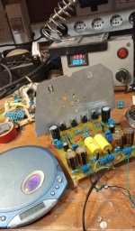
The prototype, in a single layer, is still on the work table, not having too much time for it.
The first impression is ok and thanks to the member @tortello and to the others who participated directly and indirectly in this project with tips and proposals.
Hi Knauf1919 - I like the symmetry of your layout and that the IRF610's are all on one side making it easy to get them on a common heat sink. Adding additional CRC filtering on the input power supply was helpful on my construction of Tortellos amp (see post 210). This did lower the voltage to the amp down to ~20VDC. I ordered a 20V transformer to replace my 18V to compensate for this, but have not installed it yet. One suggestion for your layout is to leave enough space for high quality input coupling capacitors, upgrading these made a noticeable improvement in sound quality on my amp. I hope you enjoy your project
")
One suggestion for your layout is to leave enough space for high quality input coupling capacitors, upgrading these made a noticeable improvement in sound quality on my amp. I hope you enjoy your project
I understand. Initially, in the first design I did so but some capacitors are extremely large. Even so they can be put on top somehow. Mundorf Evo Oil would be a happy example, but others are huge.
But I have an idea for any kind of capacitor.

Last edited:
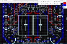
I created some space on the side. I will continue ...
I design a board that will contain the two capacitors (any model) of signal input and which will be attached to the amplifier board.
At the end of the week it will be ready. I hope you understand what I want to do.
Thanks.
I design a board that will contain the two capacitors (any model) of signal input and which will be attached to the amplifier board.
At the end of the week it will be ready. I hope you understand what I want to do.
Thanks.
Attachments
Last edited:
Yes, input caps can be huge.
Using audyn caps here (https://www.diyaudio.com/forums/attachments/pass-labs/69374d1156595926-mini-zen-head2-jpg).
Nice to see these new posts about this amp.
Using audyn caps here (https://www.diyaudio.com/forums/attachments/pass-labs/69374d1156595926-mini-zen-head2-jpg).
Nice to see these new posts about this amp.
Last edited:
Agreed!Nice to see these new posts about this amp.
I also had a small problem with PS noise. Changing transformer location and orientation made a big difference....but didn't quite eliminate it. Did not pursue it any further.
4.7uF is too much I think.
Well, this is the value given in the original paper (C2).
Now I noticed that I wrote on PCB ZTX451 instead of 450. I used ztx450 from TME.
Sorry for the mistake.
ZTX450 DIODES INCORPORATED - Tranzistor: NPN | bipolar; 45V; 1A; 1W; TO92 | TME - Componente electronice
ZTX450 Diodes Incorporated | Mouser Romania
Sorry for the mistake.
ZTX450 DIODES INCORPORATED - Tranzistor: NPN | bipolar; 45V; 1A; 1W; TO92 | TME - Componente electronice
ZTX450 Diodes Incorporated | Mouser Romania
About the power supply.
The first time I powered from a SMPS DC step down source.
There was a loud noise as a slight breeze. Afterwards, I powered from a LM338 regulator with 10000uF and I had a more pronounced 60-100Hz noise in the background. Attenuated but present ...
In conclusion, a very well filtered source is required.
Attachments
Don't know about the other builts.
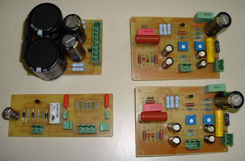
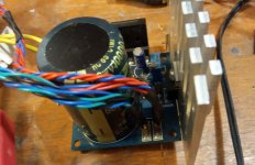
Here using the 'dual mono power supply' that was published with the amplifier.
Realized lately that the C6 capacitors (2200µF, top of the amplifier schematics) are in fact between the power circuits. Wondering how much noise they can catch there, have to move them more in the amplifier side.
Here using the 'dual mono power supply' that was published with the amplifier.
Realized lately that the C6 capacitors (2200µF, top of the amplifier schematics) are in fact between the power circuits. Wondering how much noise they can catch there, have to move them more in the amplifier side.
Hello again,
I allocated half an hour to the project. The power supply was made from an assembly with LM338 and 10000uF.
For the first time I forgot to connect GND IN to earth. So does the transformer housing.
Now everything is fine and there are no suspicious noises. I didn't have time to see the oscilloscope but I do it on the first occasion.
Good news!Now everything is fine and there are no suspicious noises.
Will you keep this power supply (LM338 and 10000µF) or try with the original one, 4700µF per branch?
In an old post about this amp Algar_emi was also using 10000µF capacitors.
According to the pics there are likely other ones but I did not find them in the parts list
My new ZEN-like headphones amp
According to the pics there are likely other ones but I did not find them in the parts list
My new ZEN-like headphones amp
Good news!
Will you keep this power supply (LM338 and 10000µF) or try with the original one, 4700µF per branch?
Yes, I will use this source. One for each channel.
It is a small source made for filament supply to vacuum tube. I think 4700uF is enough for a channel considering the current consumed.
---------------------
PS.
But how many topics are there about this amplifier? "
Attachments
Last edited:
- Home
- Amplifiers
- Pass Labs
- ZEN-like headphones amp