Acko,
So I'll take that as I don't need to cut the trace next to R3 if I'm not using R4?
That's good to know that this should work. The Amanero portion most likely won't include UFL coax, so I'm going to try and have that source very close to the OTTO board. Unless I can find some sort of Amanero to UFL adapter board of course. I feel like I've seen one in the past either in this thread or elsewhere on diyaudio.
If R3 (/2 div) is used then the trace needs to be cut and link R13 (to gnd) to shutdown the (/4 div) section. No harm leaving trace untouched but better to have less switching noise from the unused section.
There are plans for a U.FL adapter for Amanero eta~ 2-3wks with the next round of pcb fab. I can spare you one
")
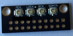
Amanero-UFL
This is available now:
Your Inbox is full!
This is available now:
An externally hosted image should be here but it was not working when we last tested it.
Your Inbox is full!
This is available now:
An externally hosted image should be here but it was not working when we last tested it.
Your Inbox is full!
Price for two pcs acko?
For the AKL-S03, it appears the oscillator Vcc pad sees voltage (2.1V) from the output power rail. I realised this when I forgot to insert a battery in the oscillator supply. Any reason why there are distinct power inputs for the source and oscillator input sections if there’s always 2.1V present at the oscillator’s Vcc pad when source power is connected? Seems to negate the benefits of independent power supplies.
For the AKL-S03, it appears the oscillator Vcc pad sees voltage (2.1V) from the output power rail. I realised this when I forgot to insert a battery in the oscillator supply. Any reason why there are distinct power inputs for the output and oscillator input sections if there’s always 2.1V present at the oscillator’s Vcc pad when output power is connected? Seems to negate the benefits of independent power supplies.
Corrected above. Output and oscillator rails seem to be partially tied.
The Output and Osc power rails are separate (hot side) but there is common gnd. The output of the Oscillator is connected to U3/U5 inputs that are on the output side power without any pull down resistor. So even if there is no power on the Oscillator there is some weak floating voltages feeding back from U3/U5. These are quite harmless and if you short the power pads of the unpowered Osc to gnd it will not cause fault. Alternatively, add a 10k pull down (to gnd) on the output of the Osc and this voltage will disappear.
@acko - just curious about usage of the BBB-DSD cape. I'm about to use mine that I acquired a few years back. The power connection can use a momentary switch, correct? Also, is it still necessary to use a backup 1S lipo battery with this cape? I believe your BBB-i2s cape needed the battery, or at least it was recommended for usage. And finally, with 5v power applied and the switch in use, the BBB won't turn on unless the button is pressed, correct? I'm just crossing all my Ts before getting this project finally going.
- Status
- This old topic is closed. If you want to reopen this topic, contact a moderator using the "Report Post" button.
- Home
- Group Buys
- Amanero Isolator/Reclocker GB