Nice transistors! Need to keep in mindDiscontinuation of the BF862 was a nightmare for us. I eventually selected Onsemi CPH3910 as a replacement and was pleased with performance. Our application is not audio, but you might give it a look.
")
I have relatively big quantity of the BF862 in my stock, but the discontinuation of them is really bad.
Some years ago I made opamps measurement in this RIAA-78 stage schematic (40dB gain at 1kHz)-
https://content6-foto.inbox.lv/albums/v/viccc/PhonoSC/PSsch.jpg
All spectrum measurements was done at 5V RMS 1kHz output signal level.
OPA627-
https://content6-foto.inbox.lv/albums/v/viccc/PhonoSC/OPA627-5V.jpg
NE5532-
https://content6-foto.inbox.lv/albums/v/viccc/PhonoSC/NE5532-5V.jpg
OPA2134-
https://content6-foto.inbox.lv/albums/v/viccc/PhonoSC/OPA2134-5V.jpg
OPA637-
https://content6-foto.inbox.lv/albums/v/viccc/PhonoSC/OPA637-5V.jpg
LM4562-
https://content6-foto.inbox.lv/albums/v/viccc/PhonoSC/LM4562-5v.jpg
All results are in good corellation with the official data sheets.
The NE5532 is good opamp, but not the best.
Viktor, Do you mean you did this with the RIAA app circuit mentioned? So this was with a gain at 1kHz of about 40dB?
Which means the distortion at gain = 1 is 40dB less?
Jan
Some years ago I made opamps measurement in this RIAA-78 stage schematic (40dB gain at 1kHz)-
https://content6-foto.inbox.lv/albums/v/viccc/PhonoSC/PSsch.jpg
All spectrum measurements was done at 5V RMS 1kHz output signal level.
OPA627-
https://content6-foto.inbox.lv/albums/v/viccc/PhonoSC/OPA627-5V.jpg
NE5532-
https://content6-foto.inbox.lv/albums/v/viccc/PhonoSC/NE5532-5V.jpg
OPA2134-
https://content6-foto.inbox.lv/albums/v/viccc/PhonoSC/OPA2134-5V.jpg
OPA637-
https://content6-foto.inbox.lv/albums/v/viccc/PhonoSC/OPA637-5V.jpg
LM4562-
https://content6-foto.inbox.lv/albums/v/viccc/PhonoSC/LM4562-5v.jpg
All results are in good corellation with the official data sheets.
The NE5532 is good opamp, but not the best.
Your measurements will be correct, which I strongly suspect. I know, the LM is better than the NE. But in the circuit configuration as notch (1kHz, + 40dB) the NE seems to have less THD than the LM. I do not know the output impedance of the notch itself, but I will investigate it again.
A candidate for your oscillator?
My discrete design in the same phono stage conditions-
https://content6-foto.inbox.lv/albums/v/viccc/PhonoSC/NewD-5V.jpg
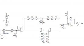
The schematic-
https://content23-foto.inbox.lv/albums/v/viccc/PhonoSC/MHNF_1.png
Real pictures of the discrete modules mounted on board-
https://content23-foto.inbox.lv/albums/v/viccc/PhonoSC/IMG-0481.jpg
RIAA is 0dB @ 1 kHz.
Yes that is the reference for the correction for lower and higher frequencies. But the gain is normally 40dB at 1kHz.
You can check it at the circuit vicnic has posted.
Jan
Yes, the gain is 40 dB at 1kHz. At the gain 0dB the distortions can be near to these 40dB less, but it depends on what configuration is used (inverting or not) and the level of the input signal.Viktor, Do you mean you did this with the RIAA app circuit mentioned? So this was with a gain at 1kHz of about 40dB?
Which means the distortion at gain = 1 is 40dB less?
Jan
Probably no. It is not so easy to build these modules. Many transistors must be matched. Will be expensive.A candidate for your oscillator?
Have you tried this composite opamp?Why not Samuel Groner's composite op-amp, the LT app note uses two composite op-amps?
Typically these opamps have unwanted side effects. We can read also about this example:
"First and foremost, it should be appreciated that the novel composite operational amplifier is conditionally stable only. Sufficient phase margin is (except at very low frequencies)only available near the unity open-loop gain frequency. The composite operational amplifier must thus be operated witha unity loop gain frequency close to the unity open-loop gain frequency. In many cases this implies the use of an additional feedback capacitor instead of a purely resistive feedback network. Large-signal overload conditions such as output voltage clipping, output current limiting or slew-rate limiting can trigger instability. Similar effects may occur during power-up and power-down..."
Have you tried this composite opamp?
Typically these opamps have unwanted side effects. We can read also about this example:
"First and foremost, it should be appreciated that the novel composite operational amplifier is conditionally stable only. Sufficient phase margin is (except at very low frequencies)only available near the unity open-loop gain frequency. The composite operational amplifier must thus be operated witha unity loop gain frequency close to the unity open-loop gain frequency. In many cases this implies the use of an additional feedback capacitor instead of a purely resistive feedback network. Large-signal overload conditions such as output voltage clipping, output current limiting or slew-rate limiting can trigger instability. Similar effects may occur during power-up and power-down..."
I am using several of these on a small DIL08 header and have seen no problems. I use a few pF across the feedback R, and I use the anti-clamp diodes as shown in the article.
By increasing the noise gain a lot I found a -160dB distortion at 1kHz, which is not as good as the -180dB Samuel reported, but then again my equipment and setup surely isn't as good as his.
Jan
opamp jockey
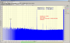
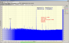
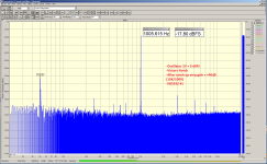
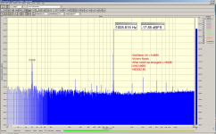
I replaced the op amp after the notch filter with other types and got unexpected results. The THD results with LM4562 are consistent but unexpectedly high. The NE5532 is not bad and has relatively little distortion. Probably because it copes well with a gain of + 40dB.
I replaced the op amp after the notch filter with other types and got unexpected results. The THD results with LM4562 are consistent but unexpectedly high. The NE5532 is not bad and has relatively little distortion. Probably because it copes well with a gain of + 40dB.
Attachments
Last edited:
Ralf, the differences are relatively minor, and I agree with you that we should expect better, for both opamps.
That suggests that something else dominates the distortion.
What power supply did you use, and what type of resistors? Is your source better than the ~-120dB implied in your measurement?
Once you get below -100dB, every electron counts! ;-)
Jan
That suggests that something else dominates the distortion.
What power supply did you use, and what type of resistors? Is your source better than the ~-120dB implied in your measurement?
Once you get below -100dB, every electron counts! ;-)
Jan
Interesting is that you get high only 2nd when LM4562 is used, but higher harmonics are lower than in the case of NE5532. Also the 2nd has different level in each example of NE5532 measurement. Needs to remember, that the second harmonic may be compensated when devices in the measurement chain have similar residual levels of them, but the phases are in opposite.I replaced the op amp after the notch filter with other types and got unexpected results. The THD results with LM4562 are consistent but unexpectedly high. The NE5532 is not bad and has relatively little distortion. Probably because it copes well with a gain of + 40dB.
Probably if you can try the OPA1656, you may get the truth
I think, you can get the full performance of this composite, when you run it only in the inverted mode. Otherwise, the input stage of the first opamp may degrade the performance. Also the relatively high input current of the input opamp can give some cons.I am using several of these on a small DIL08 header and have seen no problems. I use a few pF across the feedback R, and I use the anti-clamp diodes as shown in the article.
By increasing the noise gain a lot I found a -160dB distortion at 1kHz, which is not as good as the -180dB Samuel reported, but then again my equipment and setup surely isn't as good as his.
Jan
Interesting is that you get high only 2nd when LM4562 is used, but higher harmonics are lower than in the case of NE5532. Also the 2nd has different level in each example of NE5532 measurement. Needs to remember, that the second harmonic may be compensated when devices in the measurement chain have similar residual levels of them, but the phases are in opposite.
Probably if you can try the OPA1656, you may get the truth
Yes, Mouser always likes to deliver to me. But they always charge $20, if I order individual parts :-(
I think, you can get the full performance of this composite, when you run it only in the inverted mode. Otherwise, the input stage of the first opamp may degrade the performance. Also the relatively high input current of the input opamp can give some cons.
Yes I use it exclusively in inverting mode.
Jan
The post notch opamp's input C modulation with level will dominate its distortion. There are opamps that are much better for this specific issue. TI has an app note discussing it. Still, a discrete cascoded FET input would be the best and that becomes a forest of parts.
Post notch signal is relatively low.The post notch opamp's input C modulation with level will dominate its distortion. There are opamps that are much better for this specific issue. TI has an app note discussing it. Still, a discrete cascoded FET input would be the best and that becomes a forest of parts.
Passive twin T notch has capacitive and low output impedance at high frequencies (when the source has also low impedance).
Post notch signal is relatively low.
Passive twin T notch has capacitive and low output impedance at high frequencies (when the source has also low impedance).
I am using this mimic:
Attachments
- Home
- Design & Build
- Equipment & Tools
- Low-distortion Audio-range Oscillator