Any ideas would be greatly appreciated!
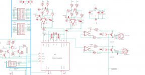
Are those really 1N4148's on the supply rails as shown on that schematic? Those don't have much of a forward current rating when they need to do their jobs. The one you need may have already opened up.
Maybe a 4001 in those locations instead?
The mute circuitry sits a little further to the left in the analog output portion of the DCX. You still have a single-ended op-amp and the differential generating section downstream.
I'm not sure why leaving the unit on all the time isn't an option. I'm not sure why folks are on/offing the power to the DCX with a power amp active. Maybe this is an auto installation or something?
Dave.
I'm not sure why leaving the unit on all the time isn't an option. I'm not sure why folks are on/offing the power to the DCX with a power amp active. Maybe this is an auto installation or something?
Dave.
But isn't there a mute function in the DCX that shorts the output when switching on/off? Was that disabled?
There is but it's utterly useless because
The mute circuitry sits a little further to the left in the analog output portion of the DCX. You still have a single-ended op-amp and the differential generating section downstream.
Hence it does not actually do anything (Edit: I actually confirmed this by shorting the output stage through AC coupling capacitor, just after the muting transistor). For muting to work correctly i'd have to put additional circuitry at the end, something which is normally muted and fast, most likely AMB style:

Which I might do anyway but I'm more concerned about possible damage to ICs due to supply reversal in principle, especially if I put something like PGA in the signal path.
Yes they are but are not the culprit, I tried replacing them with pretty beefy Schottky diodes, same story but lower voltage hump (200mV instead of 400mV). Still makes opamps swing wildlyAre those really 1N4148's on the supply rails as shown on that schematic? Those don't have much of a forward current rating when they need to do their jobs. The one you need may have already opened up.
Because leaving anything on all the time is bad practiceI'm not sure why leaving the unit on all the time isn't an option. I'm not sure why folks are on/offing the power to the DCX with a power amp active. Maybe this is an auto installation or something?
Dave.
") I've had several appliances fail this way, including this particular DCX unit. In my case the main driver IC in the PSU failed and had to be replaced.
I've had several appliances fail this way, including this particular DCX unit. In my case the main driver IC in the PSU failed and had to be replaced.Back on topic, I just can't wrap my head around the fact that 7915+cap somehow inverts its output. And if its normal transient behavior, are linear supplies are susceptible as well? I mean the topology is identical
Last edited:
The original muting transistor implementation in the DCX2496 indeed has the nonlinear load problem jan.didden described, not to mention that it doesn’t mute at the end of the output chain, so any turn on/off transient produced by the output opamps will not be suppressed. Also, the bipolar muting transistor is controlled by the firmware, after the power is turned on the transistor does not turn on to mute until the firmware boots, leaving open a time window for a transient to go through.
The JFET muting transistors across the two balanced output signals on the AMB κDCX upgrade analog board (portion shown in the schematic posted by wxn above) solve all these problems. JFETs are depletion mode devices, so they are “on” (output muted) even when the power is off, and do not un-mute until the circuit is powered up and ready. The reverse-parallel JFET arrangement cancels the nonlinearities and cuts the effective “on” resistance in half. You can see the test results using my Audio Precision audio analyzer at the “Specifications” section of the κDCX website.
Relays at the output would be good, but they are relatively large, cumbersome devices, needing a lot of current to drive their coils.
Last edited:
Thumping is one of those things that irritates tech types, but it's never going to do harm.
Maybe in the odd case where a fragile tweeter is hooked directly to a power amp. But even in that case, I'd be much more worried about power amp on/off transients than anything coming from a DCX.
Dave.
Maybe in the odd case where a fragile tweeter is hooked directly to a power amp. But even in that case, I'd be much more worried about power amp on/off transients than anything coming from a DCX.
Dave.
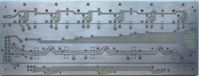
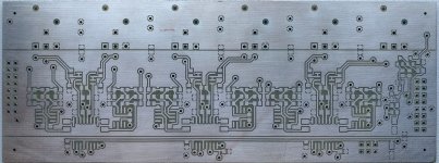
Yet another DCX2496 output board
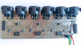
Hi everyone, after a few months of sporadic development my version of DCX2496 output board is complete. Main features:
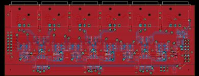
I never use analog inputs or any of the serial interfaces so I limited myself to outputs only (for input I use USB>I2S streamer, connected directly to SRC chip on DCX main board). Analog inputs (AD8510) are based on AK4396 recommended schematic, then go through DC decoupling and straight to PGA2310. After which I decided to put an impedance balanced buffer of NE5532. Ground cancelling or OPA1632 outputs would have been better but the layout got very crowded and my amps are single-ended anyway. I also included amb's muting circuit, which works wonderfully. I still get a faint click but that's OK, having in mind that I'm running amps at full 36dB gain with no attenuation. The whole analog part is sort of star grounded, all ground references for each channel come to one point on the PCB, which prevents any induced ground currents.
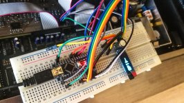
All this is controlled by a Arduino Nano, which only reads IR input, sends SPI data to the PGA and then displays gain on the display.
Technical part: all caps in the signal path are C0G grade except for the AC coupling ones which are acrylic. PCB was done on a home-made CNC, then tin-plated in a liquid tin solution. Vias were done with 0-ohm 0603 resistors in 1mm holes - a genius solution I found on the EEV forums. One lesson I learned the hard way is that low-melt solder paste is not very good for initial soldering - does not flow well and has very low surface tension. Fine for ICs though.
One thing I haven't figured out is that if I connect the ground to case I get a rising 50hz buzz, which only appears when signal is present at the SRC. So I just left the output connectors disconnected electrically from the case and the speakers are dead silent even at full volume.
I also thought about intercepting the main rotary encoder of the unit but didn't bother as remote control is always better
Hi everyone, after a few months of sporadic development my version of DCX2496 output board is complete. Main features:
- PGA2310 volume control
- IR remote control
- OLED front display
I never use analog inputs or any of the serial interfaces so I limited myself to outputs only (for input I use USB>I2S streamer, connected directly to SRC chip on DCX main board). Analog inputs (AD8510) are based on AK4396 recommended schematic, then go through DC decoupling and straight to PGA2310. After which I decided to put an impedance balanced buffer of NE5532. Ground cancelling or OPA1632 outputs would have been better but the layout got very crowded and my amps are single-ended anyway. I also included amb's muting circuit, which works wonderfully. I still get a faint click but that's OK, having in mind that I'm running amps at full 36dB gain with no attenuation. The whole analog part is sort of star grounded, all ground references for each channel come to one point on the PCB, which prevents any induced ground currents.
All this is controlled by a Arduino Nano, which only reads IR input, sends SPI data to the PGA and then displays gain on the display.
Technical part: all caps in the signal path are C0G grade except for the AC coupling ones which are acrylic. PCB was done on a home-made CNC, then tin-plated in a liquid tin solution. Vias were done with 0-ohm 0603 resistors in 1mm holes - a genius solution I found on the EEV forums. One lesson I learned the hard way is that low-melt solder paste is not very good for initial soldering - does not flow well and has very low surface tension. Fine for ICs though.
One thing I haven't figured out is that if I connect the ground to case I get a rising 50hz buzz, which only appears when signal is present at the SRC. So I just left the output connectors disconnected electrically from the case and the speakers are dead silent even at full volume.
I also thought about intercepting the main rotary encoder of the unit but didn't bother as remote control is always better
Attachments
for input I use USB>I2S streamer, connected directly to SRC chip on DCX main board
Can you provide details on how you accomplished this? Somewhere years back I posted an idea on how to do this within this forum, but never had the courage to attempt it.
Can you provide details on how you accomplished this? Somewhere years back I posted an idea on how to do this within this forum, but never had the courage to attempt it.
Well you are the author of the solution
I even remember having a chat with you about that. Yes, it works and furthermore, I2S input is immune to the dull sound bug that happens with SPDIF input.Viper_user: I wanted to make a drop in replacement, so I adapted XLR connectors. However my board isn't really balanced, cold pin is only there for impedance balance. For single ended amps that makes no difference
To anyone interested, here's the I2S wiring post:
https://www.diyaudio.com/forums/dig...ronous-usb-i2s-interface-187.html#post3677074
I've been using this for the last 6 years without problems.
https://www.diyaudio.com/forums/dig...ronous-usb-i2s-interface-187.html#post3677074
I've been using this for the last 6 years without problems.
Well you are the author of the solution
Brave move, but happy to hear it worked. Some day I will try, when I have the equipment suitable for SMT work.
Just another cable question
Hello
I'm going to buy a DCX next week. I will use it as an active crossover for a 3-way loudspeaker powered by a 6-channel AV receiver with external RCA inputs.
As input I'll use an USB to S/PDIF converter which is on it's way from China.
To avoid warranty loss I will not do any modifications - the next 3 years. Maybe I will solder a 220 resistor parallel to R15, if the adjustment causes problems.
I confess I did not read all pages and a search left me confused. So I need Your advice.
Referring to this website Sound System Interconnection, should I use:
No 4 for the digital S/PDIF to XLR In? A short 75 Ohm cable and Pin 1 and 3 shorted with a 100nF capacitor as recommended elsewhere here?
No 6 for the analog XLR Outs to analog Ins of the receiver? A 2-conductor 50 Ohm cable?
Kind regards and thanks in advance
I did it
Hello
USB to AES/EBU is working fine.
I had to attenuate the XLR to RCA outputs with a 2.2KOhm/9.1KOhm voltage divider inside the cable connectors (1%/0.6W metal film resistors).
No hum, hiss, clipping or frozen eggs syndrom.
Just an unbelievable improvement.
Kind regards
Hello
USB to AES/EBU is working fine.
I had to attenuate the XLR to RCA outputs with a 2.2KOhm/9.1KOhm voltage divider inside the cable connectors (1%/0.6W metal film resistors).
No hum, hiss, clipping or frozen eggs syndrom.
Just an unbelievable improvement.
Kind regards
Attachments
what are the minor changes without breaking the guarantee that can be performed on the DXC2496
As well as the main recommendations/settings in its usage? I'm struggling finding this information.
As an example, what i've collected so far is using the AES/EBU input instead of the analog ones.
Note: i'm using it to filter a pair of JBL XPL200 powered by a strong Crown K1 & a gentle AIWA P22 all sources connected to an EMOTIVA XMC1 and this DCX in the middle.
Thanks in advance!
Hello,
I'm no expert and my knowledge about DSP is limited.
I'm using an Acer D270 netbook to play music files (flacs).
It's sound chip is excellent. I've tested it with Holmimpulse and ARTA.
It's drawback: Digital Out only is possible via USB.
JRiver's MC, as media player, best suits my needs.
Of course I didn't want to convert a digital signal (USB) to analog (DCX-input) and again to digital (DCX-output) and again to a final analog output (AVR).
I read a lot of articles and saw brilliant work done by diyaudio members to improve the DCX digital AES/EBU input stage and make it compatible to S/PDIF.
And the very simple solution, as described above, is working fine.
I have generated a 1KHz sine wave in Audacity (amplitude 1.0) so that the clipping LEDs were flashing - both input and output.
My oscilloscope displayed a pure clean wave - no visual distortion. PC-DCX and AVR out.
So, in my opinion, there is no need to improve the DCX's AES/EBU in by using a 75Ohm to 110Ohm conversion. But for security reasons I'm reducing the volume in MC to 88%. So there is no clipping when playing files. MC is doing this through 64bit processing so I guess I'm safe here.
Secondly I don't want to use any equalizer. For now I have experimented with different types of filters, polarities and delays. I use loudspeakers that have a linear frequency response within their area of application. A good (calibrated) mike is essential. I use the volume controls of the AVR to compensate for chassis differences. That's it.
Hope this helps
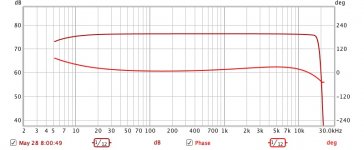
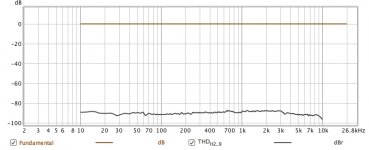
By my amateur measurements, down about 6dB at 5 Hz and about 22kHz. Phase is nice. Distortion near -90dB end to end (that's about .00005%... I don't think I could measure a piece of copper wire better).*...So, in my opinion, there is no need to improve the DCX's AES/EBU...
Makes you wonder how Behringer find room to sneak in the distortion that so many folks on this forum want to fix.
B.
*and that includes some elderly second-hand gear in the test set-up with each adding distortion and error
Attachments
Last edited:
Halo,
Can someone tell me if I can connect AES EBU to input A and an analog one to Input C at the same time? I think the answer is no but can someone confirm?
Thanks
The answer is yes.
Use the "sum/setup" and "routing" portions of the configuration scheme to set it up however you like.
Input C support either microphones (with 15 volt phantom power) or a standard line-level input.
Dave.
- Home
- Source & Line
- Digital Line Level
- Behringer DCX2496 digital X-over