Hi,@ Ostripper: These bricks feature a true active PFC. After opening one of them with a hand saw, I've found a pair of controllers by TI, one of them being a PFC controller that also monitors output current and features overvoltage protection. Later this day, when at home again, I'll have a look again and tell you the designations.
I've had a close look at my bricks again right now, and I've noticed that I wasn't right to the very extend. Yes, there are two controllers in them. One of them is TEA1751T, a combined active PFC/flyback controller, but the other one is TEA1761T, a synchronous rectifier controller that also provides overload protection.
Best regards!
I switched Q1&2, and Q5&6 with hfe at 403 and made r20,r21 from 220ohms to 300 ohms feeding Q5&6. Changed r15&16 from100 to 150 ohms feeding Q1&2 this fixed my biasing problem and I can set every to spec except my dc offset will not come down Delos 1/2 volt. Maybe change r14(2.2k)? Take r15/16 back to 100ohms?
I switched Q1&2, and Q5&6 with hfe at 403 and made r20,r21 from 220ohms to 300 ohms feeding Q5&6. Changed r15&16 from100 to 150 ohms feeding Q1&2 this fixed my biasing problem and I can set every to spec except my dc offset will not come down Delos 1/2 volt. Maybe change r14(2.2k)? Take r15/16 back to 100ohms?
Q1/2 will affect the offset. The higher Re of Q1/2 will reduce the range of the offset. 100R for R15/16 . Raise the current mirror R20/21 Re even to >300R.
You may still have a mismatch in Q1/2. Q5/6 mismatch in the mirror won't
affect offset much.
Again , next badger needs a servo
 ... lazy man's offset.
OS
Seems I traded oscillation for bad dc offset Put all resistors back to normal and cannot go lower than .5v dc at the output raised r20&21 to 470 ohms from 220 ohms it had no effect on the dc bias which remains at .5 volts for the lowest reading my CCS adjustment is at the 8.25 volts per guide. Bias at 25 MV
Now you are asking the for the same as before. Just with a different set of numbers. The answer is the same.
I've been asking twice 'cause I still didn't get the exact answer I've been asking for. I'm quite sure that there must be a formula (designing audio devices is a matter of physics!) that defines the relationship between the DC current through the output devices and the power at a given load, at least for sinusoidal signals. All I got until now just appear to be rules of thumbs.
Best regards!
Assume your amplifier is feeding a sine wave to the speaker and it have a MAXIMUM value of 1 amp.
When the voltage is positive the current will also be positive and the current will flow using the '' upper transsitor & the positive part of the power supply.
When the voltage is negative the current will also be negative and the current will flow using the '' lower '' transsitor & the negative part of the power supply.
So the current on each of the power supply will look as a half wave rectifed signal with a maximum value of 1 amp.
So maximum current is 1 amp
To get RMS value of this you mus divide by 2 ... so 1/2 amp
To get mean value of this you must divide by Pi ( 3.1416 ) ... so 0.318 amp
Had the HB running for hours. bias stays steady still have a little(.5 dc) on one channel with no hum ,amp stay relatively cool, speakers do not get hot( due to dc leakage) going to close it up and start using it. Thanks for all the advise it is a great sounding amp
Attachments
Increased input voltage, reduced HB gain?
Hello everyone.
What a wonderful community. So stoked to have found you guys and girls. Just starting my HB project. Hoping to have a unit for home that I can also use to power a bass or guitar cab. Few questions for the masses:
Planning on putting together a separate receiver board with 3.5mm, 1/4" (bass and guitar), RCA and bluetooth (eventually). Each input would/could have a basic preamp and be switched with relays into a Texas Instruments PGA2320 volume controller. I can run the PGA2320 and preamps off the 12V tap of the AnTek AN-8445.
The PGA2320 would be controlled by an MK20DX256 that read a nice weighted volume knob (recommended part numbers very much appreciated). K20 would also read an input selector knob and control the input relays and PGA2320 gains appropriately.
I'd also like to use the K20 to monitor critical voltages, temps, and currents to detect clipping or malfunction.
First Question:
Would feeding the input of the HB channels with +/- 15V and reducing the R6/3 gain resistors appropriately provide any sonic benefit?
Is this looking for trouble?
(I looked and couldnt find anything on this - sorry if we've been over it)
Second Question:
Apart from monitoring output voltage + current and rail voltage + current, are there any other nodes that would be good to monitor (and pass on to some windows logging software)?
Much love and appreciation from my end.
Cheers
/kyle
Last edited:
+/- 15V .... as power supply input ???
-under +/- 40Vdc would make a real (thermally) cool amp with the SOA to
handle 4R loads nicely.
Other than that , 30-60v per rail is the optimum.
- Changing R6/3 would alter the phase margins and other stability related factors in the design.
It could be done , but along with other changes.
So - 30-60V , and maybe under a 20% adjustment in gain. Leaving out TMC
(C8/R24) and leaving the 100pf (C7) would allow you enough margin (stability) to use any gain ratio.
OS
I'm not sure if the HB is the right amplfifier for your task. It doesn't Feature any output protection aganist overload, which is essential in an amp for (bass) guitar duties.
Maybe you'd better opt for a power amplifier that is designed for public adress/sound reinforcement? There are many examples here!
Best regards!
Maybe you'd better opt for a power amplifier that is designed for public adress/sound reinforcement? There are many examples here!
Best regards!
I took the cowards way out for an instrument amp:
TI Class D EVM Board 50% Promotion
It's a Class d Evaluation board from Texas Instruments. Hard to beat the price, somewhere between $150 and $75 depending on whether the 50% off price is in effect, and it's effortless to get working and it sounds great! But of course completely clean. Requires a Switching PSU which is about $70, And its very powerful (600w) The tiny heatsinks required are included on the boards. Of course no great guitar distortion but TI has a preamp board from the same storefront, called the "Sidegig" that adds distortion for guitar use and just plugs directly into the amp board. I guess for a bass that isn't necessary, although a pedal made for bass use might be nice.
Last edited:
Naw no class D for me. It was hard enough talking myself out of a 200 watt class A (ie a 1000 watt space heater). Hard switching has no place in voice-coils, imho.
I should clarify: by drive a bass cab I mean a single 12 (maybe 15). Speaker Detail | Eminence Speaker built into their first recommended enclosure or something. Open E string at 40 Hz can be a few dB down, no problem. I do like it when the amp reproduces running your fingers along the string and other high hz stuff
Also nothing crazy loud needed. Its an amateur blues band that plays to crowds of tens of people
In any case:
Very interested in learning what makes this topology bad for pro audio. Thought I read the frequency response was pretty broad and the topology was pretty stable.
What sort of features are we lacking here? (very new to power amplifiers)
Also still wondering if bringing the voltage gain down an order of magnitude will cause instability (R6/3 = 3k3, for example)
/kyle
Last edited:
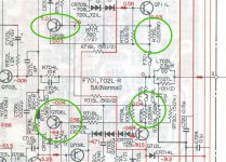
First of all , it was not designed for pro audio use. The Badger does not respond as nicely to overload (clipping) as do other designs. (below - circled) is what is included on many mid - level pro amps - the current limiter. Q705 and Q706 monitor the two .22R output resistors to reduce current if shorted. Edit - some (pro amps ) use both the limiter , fuses , AND an IC protection circuit. They don't want any warranty issues. A "listening" amp would use a 3rd party relay (or MOSFET) switch (and a IC) to monitor for DC/overcurrent and disconnect the speaker before harm is done. Crest and QSC (higher end pro-amps) use the latter.Very interested in learning what makes this topology bad for pro audio. Thought I read the frequency response was pretty broad and the topology was pretty stable.
OS
Attachments
Last edited:
First of all , it was not designed for pro audio use.
The Badger does not respond as nicely to overload (clipping) as do other designs.
OS
Fair. I'm not into clipping so maybe not a problem?
Primary goal: linear representation of the input signal; low order harmonic distortion only.
Clipping in this system would represent design failure.
Peter, I got nothing but respect for your opinion so if you say use a different amp, I'll look st it. But if I promise not to clip, can I have your blessing?
- Home
- Amplifiers
- Solid State
- diyAB Amp The "Honey Badger" build thread