Circuit "C" is simply feedback of "velocity". However, as drawn, it seems to be a simple measure of the rate of chànge of flux, the total rate being used as the control point.Thank you TNT. Yes, there is a difference, however a dual voice coil would be a perfect way to make circuit C.
I do not know why one would desire control of the rate of change of flux, when the transfer function between change of flux and acceleration has other more interesting things.
Sigh.. Whatever.
Jn

Centroid shift inward with frequency is a lowering inductance thing.
I will have to work out the reluctance force thing, I suspect it's just a simple I dL/dt thing.
The equation given in figure 6 is
reluctance force = I^2(t)*dLe(x)/dx
I assume t=time. I implemented this in my model as
F = I^2*ddt(Le(x))/ddt(x)
Not sure if I got this right, since I'm unsure about the notation. It results in an asymmetrical force on the voicecoil, trying to push it out of the magnet.
I guess if we assume reluctance force is just an expression of a Faraday force, then
F = Bl(x)*I
Where
Bl(x) = I*dLe(x)/dx
So it looks like a voicecoil with a current (or in other words a Bl) is moving into an area of different permeability. If Le is just a simple linear function of x (for the purposes of simulation), then
Le(x)/x = dLe(x)/dx
In which case we can just do
Bl(x) = I*(Le(x)/x)
Reluctance Force = I^2*(Le(x)/x)
And call it a day. Note that I^2(t) is the only time-dependent term unless Le(x) is nonlinear in which case we must differentiate which exposes the time-dependency of the differentiated harmonics.
So if Le changes by 100uH as x moves 1mm, then
100uH/1mm = Le(x)/x = dLe(x)/dx = 0.1 henry/meter
Which leaves us with
Reluctance force = I^2*0.1
So the linear component of Le(x) only causes a 2nd harmonic whose DC component tries to push the coil out of the magnet. Oddly enough a second harmonic in the Le(x) function itself actually causes a subharmonic of itself in the Reluctance force, at the fundamental frequency. This is a nonlinear mixer where it seems a lot of weird stuff can happen.
I would hate to have to solve dL/dt from all that.
I will check to see how current drive affects this distortion.
Last edited:
I feel like galaxybrain today, I'm worried I used up all my IQ for this week (or month, or year). Does galaxybrain come just before, or just after you've used up all your IQ points?
Correct me if I'm wrong, but it seems like the reluctance force comes from eddy currents in the magnet assembly.
I think we can flip this around and also see a force coming from the eddy currents in the voicecoil wire. I think these eddy currents would be on the same axis as the pole piece.
It gets a bit confusing here. If you see the eddy currents as separate from the coil current, then you see one force caused by the coil current and a counter force caused by the eddy currents. But if you see the eddies and the coil current as one current, then you see current path diameter changing and you see the force as a single force which is reduced because the diameter becomes smaller.
The difference between these is categorical, but not physical. Each is a different set of variables solved out of the same mathematical equation. It's exactly the kind of thing people tend to argue about without realizing they agree with each other.
When thinking, you must think about the physical reality. When communicating, the categorical reality is important. But if we want to think and communicate together, the categorical reality cannot be allowed to veto the physical reality. To mistake the categorical reality for the physical reality reduces the number of associative branches available for lateral thinking (In effect, it is thinking less). This is also known as the error of thinking there is Only One Correct Explanation.
Last edited:
In my simulation the magnet reluctance force distortion does not respond at all to current drive. I think that is because it is really just another form of Bl modulation. You can see it as either part of the whole Bl modulation, or as it's own modulation separate from the magnet Bl. Two different set of variables solved out of the same mathematical equation.
Static Bl modulation at least as I've implemented it also shows very little difference between voltage and current drive (It is one of the distortions which voltage drive can reduce). What can be seen is that the voltage component of re-rentrant Bl modulation on the electrical side with voltage drive is always many decibels below the distortion components on the other side of the flux loop.
So as far as Bl modulation is concerned, 8 ohms is still current drive. In order for voltage drive to reduce Bl modulation, Re must be heavily reduced. This corroborates with KSTR's comments made the last time we had a discussion on this topic.
Last edited:
Rate of change of the flux in the voice coils? Do you mean Velocity? Or are you referring to flux changes through non-linearity created by the change in the magnetic field due to compromises in the speaker motor assembly? Actually, I am still rather skeptical that this will do much, but let's see some measurements.
For the record, current drive removes the inductive component also. That is why we use it for motor drives. Of course, you knew that, but I bet that many others here didn't.
For the record, current drive removes the inductive component also. That is why we use it for motor drives. Of course, you knew that, but I bet that many others here didn't.
Some real measurements
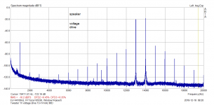
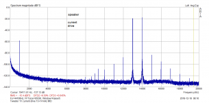
Finally, I got some useful result. Measuring 13+14kHz intermodulation, tweeter acoustical output, there is a notable improvement in H3 (almost 20dB) under the current drive, compared to voltage drive. 1V across the speaker. Again Beyma T2030.
I will need to revise my web page re current drive.
Finally, I got some useful result. Measuring 13+14kHz intermodulation, tweeter acoustical output, there is a notable improvement in H3 (almost 20dB) under the current drive, compared to voltage drive. 1V across the speaker. Again Beyma T2030.
I will need to revise my web page re current drive
.Attachments
Last edited:
It's interesting that the 1KHz product doesn't change much but the 13KHz+14KHz sidebands fall by 20db.
Yes, the 1kHz (14 - 13) product is a 2nd harmonic (asymmetry), however the "skirts" around 13 and 14kHz lines are 3rd, 5th, 7th .... all odd harmonics (symmetrical distortion).
If current drive makes good in HF but is a problem at LF (resonance) - it should be possible to make the feedback frequency dependent so that one uses low impedance around driver resonance and then go to current drive higher up - no? (Thinking about my XO less line source with 16 fullrange drivers)
//
//
Last edited:
== 18sound AIC
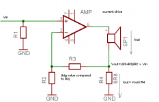
We discussed this already I seem to remember. To exploit it fully, I would think the stator coil should be driven with a (probably scaled) copy of the actor coil current (again), not just applying a voltage. This should fully cancel any BL(i) and Le(i) which is a dominant distortion source for PA power midranges (especially with horn loading).
Exactly. This is the feasible real-world appliciation of current drive with typical drivers under typical acoustic loading which results in a high-Q system resonance.... too high and too unstable to be EQ'd out and often too high to be free of chaotic "jump resonance" problems under large excursion. The damping applied doesn't need to be choosen so strong as to give flat SPL (as per being <= 0.71), it is enough to arrive at a system Q of no higher than 3 or so which can be EQ'd reasonably. This will ring slightly for external signals applied to the cone (including its own distortion) but it doesn't sacrifice too much of the current-drive properties. A compromise, as always.If current drive makes good in HF but is a problem at LF (resonance) - it should be possible to make the feedback frequency dependent so that one uses low impedance around driver resonance and then go to current drive higher up - no? (Thinking about my XO less line source with 16 fullrange drivers)
//
EDIT: Of course each driver should ideally have its own amp, since both parallel and series connection will skew the results unless drivers are very well matched. Again, compromise...
Last edited:
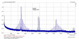
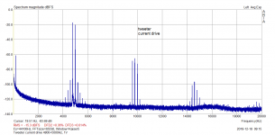
Tweeter, twin tone intermodulation 4800+5000 Hz. This is really amazing!
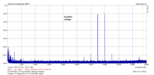
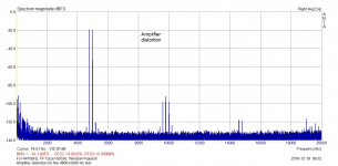
P.S.: amplifier distortion added.
Very interesting. I did current drive experiments looking at just THD and wasn't convinced it had much to offer. Will now do the same looking at multi tone. Thnx.
Very interesting. I did current drive experiments looking at just THD and wasn't convinced it had much to offer. Will now do the same looking at multi tone. Thnx.
Thank you. I also did THD before, without a notable result. Twin tone with closely spaced tones is nice, as it enables to distinguish, very quickly, between even and odd harmonics, without messing them together.
The 4800+5000 shows both intermodulations and harmonics, again easily distinguishable between even and odd ones.
Tweeter, twin tone intermodulation 4800+5000 Hz. This is really amazing!
P.S.: amplifier distortion added.
Splendid!
Maybe a new ABX to confirm the value
?//
Not velocity, rate of change of flux. They are not exactly the same due to non linearities.Rate of change of the flux in the voice coils? Do you mean Velocity? Or are you referring to flux changes through non-linearity created by the change in the magnetic field due to compromises in the speaker motor assembly? Actually, I am still rather skeptical that this will do much, but let's see some measurements.
For the record, current drive removes the inductive component also. That is why we use it for motor drives. Of course, you knew that, but I bet that many others here didn't.
If anybody wants to see the difference between my drive and current drive, just run the drive coil in current mode and look at the difference signal between the two lower terminals of the coils. Any harmonics that appear are those current drive cannot prevent or control.
Jn
Exactly. This is the feasible real-world appliciation of current drive with typical drivers under typical acoustic loading which results in a high-Q system resonance.... too high and too unstable to be EQ'd out and often too high to be free of chaotic "jump resonance" problems under large excursion. The damping applied doesn't need to be choosen so strong as to give flat SPL (as per being <= 0.71), it is enough to arrive at a system Q of no higher than 3 or so which can be EQ'd reasonably. This will ring slightly for external signals applied to the cone (including its own distortion) but it doesn't sacrifice too much of the current-drive properties. A compromise, as always.
EDIT: Of course each driver should ideally have its own amp, since both parallel and series connection will skew the results unless drivers are very well matched. Again, compromise...
Snap, done in 1990 and it works well.
Howie
If anybody wants to see the difference between my drive and current drive, just run the drive coil in current mode and look at the difference signal between the two lower terminals of the coils. Any harmonics that appear are those current drive cannot prevent or control.
Jn
I got exactly the same result, re distortion, with current drive and with my simulation of your drive. However, I assume you consider my simulation of your idea invalid, so let's wait if someone gets a different result (Keantoken?), or better, if someone measures something related to distortion on a double coil speaker, however the last option might take ages, IMO.
- Status
- Not open for further replies.
- Home
- Member Areas
- The Lounge
- John Curl's Blowtorch preamplifier part III