The best way to know if the sim is realistic or not is to run it and analysed the results, but may be I'm wrong on this statement.
Of course. But it is not unusual for two people who have difference of view to get a different conclusion from an analysis. ;-)
Jan
Post 1028 explains what is happening. Transconductance is happening, but the Early Effect is significant, because the loop gain is so high that it drives vbe to such low levels that the contribution from transconductance is on the same order as that from the Early effect (the loop gain doesn't reduce vce.) So now we have an additional (effectively resistive) path from the emitter to the collector.
Just so it is clear to everyone you can lookup at least 1 commercial op-amp that has been around for decades where the Early effect has no contribution to the open-loop response above 10Hz or so (AD846). The idea that the fundamental description of a circuit depends on implementations at a particular point in time is curious. That is a current source has an infinite output impedance but I have no circuit elements that can quite make such a thing so a current source as a concept does not exist.
Just so it is clear to everyone you can lookup at least 1 commercial op-amp that has been around for decades where the Early effect has no contribution to the open-loop response above 10Hz or so (AD846).
I don't doubt it, but haven't confirmed it.
The idea that the fundamental description of a circuit depends on implementations at a particular point in time is curious.
If you think I have claimed this, I don't recognize the claim.
That is a current source has an infinite output impedance but I have no circuit elements that can quite make such a thing so a current source as a concept does not exist.
There are no such physical things as ideal current or voltage sources; neither zero nor infinite impedance sources exist.
I thought of Muses.Forr "I learned to be wary toward advertisement. Some ICs are advertised as being specially made for audio. How could they ? What's the recipe ? Do customers effectively find them better than standard op-amps in rigourous tests ?"
--
I would use a NE5534 or LM4562 (both advertised for audio) and never use a 741. Some opamps are optimised for audio - noise, distortion etc.
NE5534 or LM4562 are suitable for audio but they have certainly been conceived for much larger applications than audio.
I have never stated current feedback topology sounds better. Kindly find the statement - anywhere - and I will apologize unreservedly for making it. You may have inadvertently got this impression from a previous member who claimed (on many occasions without giving proof when challenged) I made this statement. I never have and have gone to ains to remain completely neutral on the matter.
post #1055 RNMarsh "i said CMA/CFB amps sound better almost always."
post #1056 Bonsai "
") "
"Is your smiley not a sign of agreement ? Don't mind, I apologize, I am quibbling.
Very puzzling explanation of the CFA core. What is the ultimate control ?The voltage at the inverting input equals the non inverting input because current flowing through Rg and Re raises or decreases the inverting input voltage, unlike a VFA where the current is of no consequence (because the inv. input impedance is very high. That's why its called a CFA - not because the input voltages are equal in the linear mode.
Taking a CFA circuit with one transistor input DC loaded by a CCS :
The current coming from the output through Rf has a minuscule lag behind the current coming from the inverting input which defines the voltage across Rg.
There are two inseparable functions of the input transistor at work :
- the voltage across Rg is established by the property of voltage following of its emitter.
- the current it delivers is established mainly by its base-emitter voltage.
As soon as a voltage signal appears at the base,
- it is replicated at the inverting input.
- the current circulating in the transistor increases.
- the voltage across Rg increases.
- the signal on the collector is amplified by the remaing part of the circuit to the output, the path introducing the minuscule lag.
The current through Rf is determined by the difference of voltages between the output and the inverting input (= across Rg) .
The loop of the circuit forces the output voltage (= entry of the feedback divider) to be such that the voltage across Rg is the replicaton of the signal voltage at the circuit input.
Currents from the inverting input and through Rf are of same polarity, they add across Rg. So the inverting input has (a lot) less current to supply and the input stage works in good conditions of linearity.
The involved currents in the feedback process obey to a voltage.
Last edited:
If you think I have claimed this, I don't recognize the claim.
Yes you did, I said simply cascode the input devices and you said, "but no commercial op-amps do this". There are in fact hetero-junction devices with huge Early voltages, if you don't see dropping new devices into the same circuit does not fundamentally change the entire theory of its operation I don't know what to say.
If the input devices are pure transconductances it is still a CFA. Or consider beta is always finite so there is always input current on a VFA this does not matter it's still a VFA.
Last edited:
Chris,
I promised to come back on your math. But in the meantime so many postings have been made, that I had to absorb those first.
I must say that I'm fully on Scott's side and have some problems in understanding the impact of your arguments.
But without going into details where and when Ro, Hfe or whatever imperfection are playing a role and whether it is something to worry about or not, I'm in favour of measuring the circuit with current and voltage injection techniques as Sergio Franco and Walt Jung were practising at the end of Sergios publication for EDN.
https://www.edn.com/design/analog/4458753/3/In-defense-of-the-current-feedback-amplifier
By doing that, three transimpedance T curves can be obtained.
Ti by means of current injection, Tv with voltage injection and the loop gain T.
When the FR plot of Ti is close to T's plot, it is a CFA.
When the FR plot of Tv is close to T it is a VFA.
When Ti and Tv are equal, we have 50% CFA and 50% VFA.
1/(1+T) = 1/(1+Tv) + 1/(1+Ti)
In this model everything can be investigated, like the effect of an impedance at the inverting input, early effect etc, etc.
As long as Ti is much closer to T, it definitely is a CFA.
If we can agree on that, the discussion has made a Quantum leap forward.
Hans
forr,
A smiley does not mean I make statements like ‘CFA’s sound better’. Richard is passionate about them and I like that. But I am quite circumspect about making claims without double blind testing to prove it. Which does not mean I don’t have subjective opinions BTW.
5534/4562 - yes they can be applied as GP opamps, but I think the audio requirements took precedence - just look at the specs.
CFA is a voltage output amplifier. Yes. Or a current output amplifier.
CFA operation relies on voltage feedback: Naaah. Sorry, I’m never going to believe that one!
Anyway, good freindly discussion - we will have to agree to disagree
Last edited:
Yes you did, I said simply cascode the input devices and you said, "but no commercial op-amps do this". There are in fact hetero-junction devices with huge Early voltages, if you don't see dropping new devices into the same circuit does not fundamentally change the entire theory of its operation I don't know what to say.
This durn communication on this thread again! Classical, commercial CFAs don't do this. Post 1028's sim does not. The sim you offered does not.
Of course any circuit that cascodes minimizes Early. I have never (intentionally) questioned this.
If the input devices are pure transconductances it is still a CFA.
Never contested (again at least not intentionally). The point always was that "voltage feedback" depends on pure transconductors (at least it seems so to me.) But a Classical CFA's inverting input transistor does not act this way. So pure transconductors would still be CFAs, but without cascoding, they don't exist. This makes the "voltage, not current" feedback claim even more challenged.
Oh Oh. someone just took over the current mode amplifier name.
Questyle - Questyle Technology Introduction
-RNM
Questyle - Questyle Technology Introduction
-RNM
It's not that you can't find a needlessly complex way to describe this phenomenon as voltage feedback; it's that you can more simply describe it as current feedback.
Post 1028 summary: The voltage feedback paradigm demands that the transistor is acting mainly as a transconductor. In a transistor, transconductance gm is I(DC) / 26mV at room temperature. That means that the ratio of AC parameters ic/vbe should equal gm. But if you measure it in the Post 1028 sim or in Scott Wurcer's sim, it definitely doesn't.
Post 1028 explains what is happening. Transconductance is happening, but the Early Effect is significant, because the loop gain is so high that it drives vbe to such low levels that the contribution from transconductance is on the same order as that from the Early effect (the loop gain doesn't reduce vce.) So now we have an additional (effectively resistive) path from the emitter to the collector.
Of course you can say that this is voltage feedback because the voltage between the emitter and base drives a transconductance to create a current which is added to another current created by the difference between the emitter and collector voltages divided by what is effectively a resistor to become a single current flowing through the collector.
Or, noting that the emitter and collector currents are almost identical, you can say you have current feedback.
It's not necessarily wrong to describe this as voltage feedback (see 2 paragraphs above), but even without the Early effect, it's less complex and more straight forward to describe it as current feedback. With the Early effect, there's no comparison.
Thank you for the explanation. I understand now why I didn't understand it before.
Your reasoning is based on the behaviour of the input stage transistor.
The problem is that if we change the schematics of the input stage, adding a cascode for example, your reasoning is wrong.
I don't care of the internal scheme of the CFA. For me it is a black box with one output depending of the difference of two input, where one input is low impedance and where the gain depends on what is connected to inverting input.
My reasoning is very simple :
If you design a feedback network which behaviour is current source, the CFA will not work.
If you design a feedback network which behaviour is voltage source, it will work.
It will work because inverting input will see a low impedance and the amplifier will have open loop gain.
If feedback network is current source, inverting input will see a high impedance and the amp will not have high open loop gain.
Then, the conclusion is evident : we are not in presence of current feedback.
This is really getting silly.
Can we agree that an ideal so called "current source" has infinite impedance?
That a so called ideal "voltage source" has zero output impedance?
Than since we do not have "ideal" building blocks in our real world, we nevertheless are allowed to call them voltage or current sources, as long as these are qualitatively close to the respective ideal value?
If yes, I think we can safely call a CFA a CFA, as it's negative input _ideally_ should have zero impedance, and VFA's negative input should _ideally_ have infinite input impedance.
If we are allowed to distiguish voltage and current sources in our non-perfect world calling them what they "almost" are, HOW ON EARTH are we not allowed to call these two amplifier / feedback topologies differently?
That's the nail on the head.This is really getting silly.
In this life nothing is ideal but we keep trying to improve, to get as close as possible to our ideals.
Hans
Chris,
I promised to come back on your math. But in the meantime so many postings have been made, that I had to absorb those first.
I must say that I'm fully on Scott's side and have some problems in understanding the impact of your arguments.
Perhaps you can help me understand how Scott's arguments apply to my claims, because I don't.
But without going into details where and when Ro, Hfe or whatever imperfection are playing a role and whether it is something to worry about or not, I'm in favour of measuring the circuit with current and voltage injection techniques as Sergio Franco and Walt Jung were practising at the end of Sergios publication for EDN.
https://www.edn.com/design/analog/4458753/3/In-defense-of-the-current-feedback-amplifier
By doing that, three transimpedance T curves can be obtained.
Ti by means of current injection, Tv with voltage injection and the loop gain T.
When the FR plot of Ti is close to T's plot, it is a CFA.
When the FR plot of Tv is close to T it is a VFA.
When Ti and Tv are equal, we have 50% CFA and 50% VFA.
1/(1+T) = 1/(1+Tv) + 1/(1+Ti)
In this model everything can be investigated, like the effect of an impedance at the inverting input, early effect etc, etc.
As long as Ti is much closer to T, it definitely is a CFA.
If we can agree on that, the discussion has made a Quantum leap forward.
Hans
This is rather amusing. I made precisely the argument above in Current Feedback: Fake News or the Real Deal? | audioXpress . Whatever have I written to make you think that I might oppose this?
Perhaps I have been unclear about the purpose of my statement. It seems to me that the Claim of "voltage feedback, NEVER current feedback" is dependent on the assertion that the inverting input transistor in a CFA acts predominantly or even exclusively as a perfect transconductor. I have merely pointed out that it doesn't, making the Claim even less tenable.
Thank you for the explanation. I understand now why I didn't understand it before.
Your reasoning is based on the behaviour of the input stage transistor.
The problem is that if we change the schematics of the input stage, adding a cascode for example, your reasoning is wrong.
Thank you for your reply. But I think you're assigning the "problem" to the wrong place. Yes, if you cascode the input stage, you minimize the effect of Early. But the "problem" is that if you don't, and you deal with the classical CFA as represented by either of the two sims I mentioned, your "voltage feedback" claim fails. Shouldn't your description of how a CFA operates cover all CFAs, especially classical ones? When you find an example which refutes the theory, reject the theory.
My reasoning is very simple :
If you design a feedback network which behaviour is current source, the CFA will not work.
If you design a feedback network which behaviour is voltage source, it will work.
It will work because inverting input will see a low impedance and the amplifier will have open loop gain.
If feedback network is current source, inverting input will see a high impedance and the amp will not have high open loop gain.
Then, the conclusion is evident : we are not in presence of current feedback.
The observation is correct, but I don't believe that your conclusion is supported by it. Except, of course, for all of the real world CFAs which see infinite impedance feedback networks - of which there are none.
In post 1266, Hans cites Middlebrook's technique for determining whether there is more current or voltage feedback in a loop. In the first part of my article Current Feedback: Fake News or the Real Deal? | audioXpress, I point out that when you apply this at the inverting input of an op amp, this simplifies approximately to whether the impedance presented by the feedback network to the input is greater than that of the input or not. If it is, we have predominantly current feedback; if not, predominantly voltage feedback.
Note that it is possible, and in fact some CFA manufacturers suggest, that for certain gains, the network impedance actually be less than that of the inverting input. So they recommend in these cases to operate the IC with predominantly voltage feedback!
Obviously, we're not going to call this a VorCFA, but we'd like to name the topology.
So here's another observation: for all CFAs, the signal current flowing through the collector is not merely approximately equal to, but is in fact entirely supplied by, the current presented by the feedback network back to the transistor emitter. Hence, current feed back.
Hi Chris,
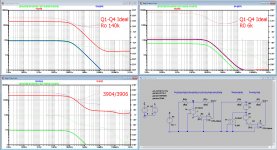
I did what I proposed yesterday and simulated the way Sergio Franco and Walt Jung did.
I used 3 versions: the first your original version with the 2N3904/3906.
Second, the input buffer Q1-Q4 equiped with ideal transistors, all others as before. this time with an Ro of 140K, being the resistor caused by the early effect.
And Third, as number two, but now with an Ro of 6K.
In the graphs below, the green line is the ideal transfer T, Blue is the transfer when injected with a current Ti and Red is when injected with a voltage Tv.
As long as Blue is very close to Green and an order of magnitude from Red, we have a CFA.
The other way round is a VFA. When Blue and Red are equal, we have 50% CFA and 50% VFA.
In your case with the 2N3904/3906 it is definitely a CFA.
It is still a CFA with and ideal inpur stage, shunted by 140K early effect resistors.
Only when Ro becomes 6K, VFA and CFA are equal and we no longer have a CFA.
So in your case, I see no reason why your 2N3904/3906 cannot be fully reckoned to the CFA category.
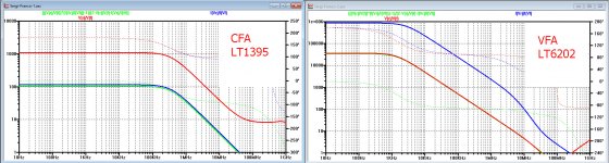
I will still come with an example of a LT1395, a pure CFA and a LT6202, a fast VFA.
Hans
I did what I proposed yesterday and simulated the way Sergio Franco and Walt Jung did.
I used 3 versions: the first your original version with the 2N3904/3906.
Second, the input buffer Q1-Q4 equiped with ideal transistors, all others as before. this time with an Ro of 140K, being the resistor caused by the early effect.
And Third, as number two, but now with an Ro of 6K.
In the graphs below, the green line is the ideal transfer T, Blue is the transfer when injected with a current Ti and Red is when injected with a voltage Tv.
As long as Blue is very close to Green and an order of magnitude from Red, we have a CFA.
The other way round is a VFA. When Blue and Red are equal, we have 50% CFA and 50% VFA.
In your case with the 2N3904/3906 it is definitely a CFA.
It is still a CFA with and ideal inpur stage, shunted by 140K early effect resistors.
Only when Ro becomes 6K, VFA and CFA are equal and we no longer have a CFA.
So in your case, I see no reason why your 2N3904/3906 cannot be fully reckoned to the CFA category.
I will still come with an example of a LT1395, a pure CFA and a LT6202, a fast VFA.
Hans
Attachments
Yes you did...
So from your point of view, with my explanations/clarifications, are we at least approaching consensus?
Hi Chris,
I did what I proposed yesterday and simulated the way Sergio Franco and Walt Jung did...
Hans
Hans, you seem to be trying to convince me of something that I never contested. Why? Please see my post of a few minutes ago. "What we have here is a failure to communicate."
That is what I was afraid of all the time.Hans, you seem to be trying to convince me of something that I never contested. Why? Please see my post of a few minutes ago. "What we have here is a failure to communicate."
I had difficulties in understanding the significance of your point in #1228, and had the feeling that the Early Effect plays no role at all, which is now proven by my sims.
Hans
- Home
- Amplifiers
- Solid State
- Current Feedback Amplifiers, not only a semantic problem?