TIC,
Oliver sent me the schematic for the UHS Buffer.
Also the 74HC02 Schematic so you can make your own.
UHS Buffer - Google Photos
Oliver sent me the schematic for the UHS Buffer.
Also the 74HC02 Schematic so you can make your own.
UHS Buffer - Google Photos
The key is... WaveIO outputs I2S, and Red Baron expects to receive I2S. So make the connection and you are in business. The options for connecting are with U.FL cables (preferred) or by unshielded wires. Toslink is a competing interface to I2S. BNC is a type of connector that would compete with U.FL.
Also the 74HC02 Schematic so you can make your own.
I have a couple of those 74HCO2 buffer boards that I bought way back when but never got round to using. :<(
I'll not be using them now - if anyone wants one, PM me. Yours for the price of the stamp.
Dave
PS: wlowes - good to see you around.
Building
I have started building the Red Baron and so far so good.
Rectification, Done!
Shunt board, Done!
Red Baron, done and the rest is ongoing (waiting for components).
I have on the shunt board -15.30 volts, -5.501 volts and +5.502 volts stable after 10-15 minutes. I had to change one of the heatsinks for the 15 volt rail cause it got really hot (toutchable for 3-5 sek) but it turned out that the sinks that I recieved in the package (bought from another earlier buyer) was only 40 mm high and luckely I had some 50 mm sinks laying around so now I am good.
Still missing the 3.3 volt line cause I am missing parts but I was wondering if there are substitutional part for the DX45H8 that was recommended in the rebuild of a 5 volt line?? I have problem locating this DX45H8 locally and was thinking that there must be substitutes?
I connected the Red Baron board for the first time last night and measured some voltages on the board to confirm function, I had, without the TDA chip installed and no load, on pins;
15 - 5.529 volt
16 - 5.527 volt
17 - -5.521 volt
26 - 15.28 volt
27 - 15.28 volt
28 - 15.29 volt
just wonder if someone can confirm the values here.
I also have a question about the DC Reference board, it says 470 uF caps but would it be possible to use 330 uF Nichicon Muse here (have them home and don't want to spend money if not needed)??
Finally, I am setting up a Salas Reflector D for 5 volt for the Twisted Pear WM8804 and Waveio boards, would it be sufficient with 4700 uF cap instead of 10000-22000uF that is recomended from Salas or is it tooooo small a cap??
Is there anyone who know what current draw I should expect from the WM8804?
Information from Cirrus Logic just state that the chip itself draw 2.6-3.7 mA but it doesn't say anything at TP site about total use??
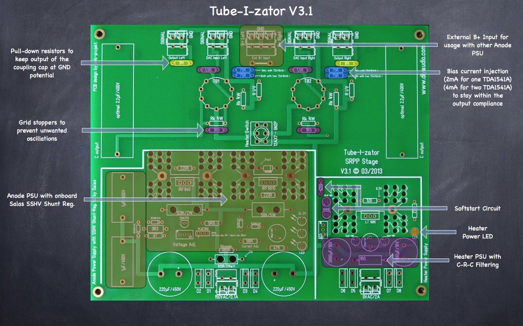
Need help regarding the Tube I zator board.
What and where to measure with the adjustment of the trimmer on the board?
Thanks
Kp93300
Wrong thread...
") Anyway, all measure points are painted on the PCB and will be measured to GND.
Anyway, all measure points are painted on the PCB and will be measured to GND. Tube-I-zator Professional PCB

Everything is built, starting to put it all together & testing.
I have a spare Shunt regulator Module for add. +5V line. I want to use it for powering up a WaveIO board. I have a + / - Power Supply built so what I am looking for is the formula / resistor value for R1 to get 500mA.
As it was originally set up with a 10 ohm Resistor to get 200mA. Does the equation: CCS(.200A)=x/10 in Ohm where apply here? Where x=2. If so 500mA CCS would be: .5= 2v / 4 Ohms. Could someone please check my math against what they have done?
Oliver, can I safely set my current overhead to 600mA with the spare Shunt regulator Module for add. +5V? My calculations puts that around 3.3R and I have a 3R3 KIWAME 5W in stock.
Thanks,
Aguaazul
Everything is built, starting to put it all together & testing.
I have a spare Shunt regulator Module for add. +5V line. I want to use it for powering up a WaveIO board. I have a + / - Power Supply built so what I am looking for is the formula / resistor value for R1 to get 500mA.
As it was originally set up with a 10 ohm Resistor to get 200mA. Does the equation: CCS(.200A)=x/10 in Ohm where apply here? Where x=2. If so 500mA CCS would be: .5= 2v / 4 Ohms. Could someone please check my math against what they have done?
Oliver, can I safely set my current overhead to 600mA with the spare Shunt regulator Module for add. +5V? My calculations puts that around 3.3R and I have a 3R3 KIWAME 5W in stock.
Thanks,
Aguaazul
Hi Aguaazul,
I= U/R so
2V/3.3R=0.6A...correct.
As Salas said, the reg. could go up to 1A. Please use a bigger heatsink!!!
Best,
Oliver
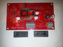
I read the files were lost in a HD crash, is there any chance that the PCB Fab might still have these files?
Sadly as the Red Baron is out of production is there an alternative board available anywhere?
I've got some TDA1541A's I want to play around with.
I have one available from his personal system. A couple of rev's back but perfectly useable. If you want it, PM me. Alternative would be Ryanj's Distinction board.
Attachments
Hello
I want to use the WM8804 to replace the CS8412 in my NOS TDA1541 dac.
Since WM8804 are cmos 3.3v out and the TDA1541 are TTL 5v I2s input, I would use buffers for the 3 I2s signals between the WM8804 and the TDA1541.
I have many 74AC04, but it would invert the signal, can I use two 74AC04 in serial for each I2s signals, so it would buffered without inverting the I2s signal ?
Thank
Bye
Gaetan
No sound, no fun!
I am owner of the Red Baron DAC and I have put all parts together but I have a big problem, it will not play.
I mean I get nothing out of this device and since I am entirely newbie when it come to digital signals I don’t even know where to start.
I have checked and dubble checked the PSU and I have +5.3 V, -5.3 V and -15.3 V from Olivers big shunt board. I have another shunt of Olivers that is rebuilt to deliver 3.3 V and finally a Salas ReflectorD for another + 5.25 V. Olivers Shunts are delivering juice for the DAC while the Salas ReflectorD is dedicated for the Waveio and Twisted Pear WM8804. Right now I am just trying to get some sound out of this device, don’t know if it is to be called DAC until it has proven that it can in fact do the work as DAC. I have just connected the Waveio board since I couldn’t get the TPA running either and from what I have been reading here in the thread it seem that the easiest input is the Waveio, straight forward and no fuzz….. but not for me, I have no music.
Should I give up or is there still hope? I got the drivers for Waveio today from Lucien at Luckit since I had bought the Waveio as second or third user and didn’t have the drivers for Windows, everything installed without problem but still no…. sound.
I also have the Tube-I-Zator but I don’t want to mix that one in this mess until I have sound from the DAC, then I can implement the Tube-I-Zator also but that will be later…. Just as implementing the Spdif with a switch between the TPA and Waveio, that will be later. First step is to get sound out from this DAC.
I am usually not stuck like this but when it come to digital signals and since I am only owner of a DMM, not any Oscilloscope, I feel like a stranded whale, I can just watch and listen but I don’t know what to do, is there anyone who are willing to help to get this working??
no sound no fun is very true
don't know if this helps, when I got no signal from the Red Baron, the problem was that my input signal I2C was too weak. everything was hooked up properly, voltages etc., but the signal was below the threshold for the TDA1541A to "work".
one thing you can test is having less attenuation, my Red Baron an older version than yours has 5x 100 ohm in series resistors, you can test by jumping them.
at some point I had also a 74HC125N buffer in, can't remember if it was for the bit clock, or word clock...
seeing how much you invested in power supply, red baron, wave io, I/V stages... for your troubleshooting having an oscilloscope would definitely help, i got mine for 25 eur on ebay plus shipping of course it's pretty shabby, but you see if you have signal or not
good luck
Martin
don't know if this helps, when I got no signal from the Red Baron, the problem was that my input signal I2C was too weak. everything was hooked up properly, voltages etc., but the signal was below the threshold for the TDA1541A to "work".
one thing you can test is having less attenuation, my Red Baron an older version than yours has 5x 100 ohm in series resistors, you can test by jumping them.
at some point I had also a 74HC125N buffer in, can't remember if it was for the bit clock, or word clock...
seeing how much you invested in power supply, red baron, wave io, I/V stages... for your troubleshooting having an oscilloscope would definitely help, i got mine for 25 eur on ebay plus shipping of course
it's pretty shabby, but you see if you have signal or notgood luck
Martin
Last edited:
Agree with the previous suggestions. Also work through the basics with your multimeter. Check that you have proper voltage at the power pins of the 1541a, and the DEM circuit. In my experience, if the 1541a has voltage and there is an I2S signal there will be music. Of course check that you have grounds connected everywhere there is a ground.
I forget the details of WaveIO, but are there LED's to indicate that it is powered and running correctly? I believe you can look at the driver to ensure it sees a DAC and is playing.
I forget the details of WaveIO, but are there LED's to indicate that it is powered and running correctly? I believe you can look at the driver to ensure it sees a DAC and is playing.
Wow, this thread is defenitely not dead, a lot of ideas emediately.
I will start working through some of your ideas right now and see what I can come up with. I did forget to tell that my DMM has possibility to measure frequency also, what that does mean in reality I don't know since I have never used that setting but it measure Hz. I do think that I could at least see what clock frequency that are going through the different connections.
I have some downloading to do now so I will be back. Tnx!
The WaveIO has two leds (my version at least) indicating if it is working properly. I have had a WaveIO working perfectly with a Red Baron PCB.Agree with the previous suggestions. Also work through the basics with your multimeter. Check that you have proper voltage at the power pins of the 1541a, and the DEM circuit. In my experience, if the 1541a has voltage and there is an I2S signal there will be music. Of course check that you have grounds connected everywhere there is a ground.
I forget the details of WaveIO, but are there LED's to indicate that it is powered and running correctly? I believe you can look at the driver to ensure it sees a DAC and is playing.
Some early morning work
I did check all incoming power and I was little on the high side when measured directly on pins 15, 26 and 28 on the TDA chip.
All ajusted to -15.100 V, -5.200 V and 5.200 V so they should be correct, I can even take them down further since it says 14.5 -15.5 V respectively 4.5-5.5 V in the data sheet with center just on -15 V, -5 V and 5 V.
Also checked for continuity from Waveio and DAC chip and here is something I don't understand. I am running the Red Baron in I2S mode and when putting a probe on Pin1, which shuld be WS I can measure continuity with the other probe both on WS from Waveio but also DT, which should be Data, is it supposed to be like that??
Lastly, I was thinking about the DEM oscillator and earlier in this thread (don't have the quote right now) it was asked if the 2.2 nF cap was correct since in many other applications it is just 680 pF. Was there ever an answer to this question??
My Waveio only have one LED but I will tonight connect LEDs for Host Found and Music Streaming so I can see what happens when I send a signal through.
I also tried downloading the VA program which seem rather ok even if I found links at DIY Audio which was talking about the quality level of the program. But for a rough estimate I think it can be ok but here come a question, are there any interfaces ready to buy cause without an interface where I can connect probes it is not for any use or do I have to build the interface myself, is it possible still to buy pcb:s and ready packages for the program??
Last edited:
- Status
- This old topic is closed. If you want to reopen this topic, contact a moderator using the "Report Post" button.
- Home
- Group Buys
- "Reference" TDA1541A DAC with I2S-BUS architecture