as_audio,
I don't used a cap for filter the zener. Monte MCguire already explained that.
But...
For noisy high voltage ones, a cap *perhaps* can be a must. And even the interactions with load can mess things. I always bypass the output from regulators due to this, even if theory says otherwise. Some time ago I needed to bypass a zener with a small cap due to some interaction with the transistor following it making it to oscillate, probably due to a problem related with layout, load or both. Or even a very sluggish diode "driving" a fast transistor make oscillations, perhaps...
I need to measure for myself, but various sources mentions high noise with high voltage zeners, higher than gas stabilizer tubes (Morgan Jones verified this but against a string of low voltage zeners). Also, for long string like that mentioned the dynamic impedance is high.
Last edited:
as_audio,
I don't used a cap for filter the zener. Monte MCguire already explained that.
But...
The noise reduction works the same with low voltage zeners.
Of course making the transistor to oscillate... for clarificationas_audio,
.... Some time ago I needed to bypass a zener with a small cap due to some interaction with the transistor following it making it to oscillate,.....
")
With complete attached load circuit (preamp stage) is difficult to see if bypass is related to zener alone or if is a load interaction. Some people love to use unbypassed gas tubes or even zener in some stages but forget that in HF/RF the active circuits interacts with PSU and make some extra noises (and sometimes oscillations), and this vanishes even with a low valued capacitor. High impedance at RF also can attract some noises. But testing in isolation, for reducing intrinsic noise with low Z diode one needs a low Z cap, and for LF only a big cap will have low Xc for helping that, or isolate the diode with a series resistor.The noise reduction works the same with low voltage zeners.
The noise reduction works the same with low voltage zeners.
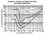
The dynamic impedance of a zener depends on its breakdown voltage, and according to simple network theory, the filtering effectiveness of a shunt filter cap will then vary according to the zener voltage.
For zener voltages near 6V, the dynamic impedance is orders of magnitude lower than zeners with an avalanche of 3V. Zeners are not all one thing - there is the zener breakdown effect and the avalanche breakdown effect, and varying combinations of each are used to manufacture "zener" diodes of specific voltages. Not so important here, but the two effects also have opposite temperature coefficients, so an optimal blend of both effects will result in a "zener" with very low temperature coefficient.
Attached is a graph from a Motorola zener datasheet showing the range of dynamic impedance vs. zener voltage.
Again though, for zeners around 6V, their dynamic impedance will be very low, so their internal noise will only be able to be filtered with a large capacitor. It's simple network theory and what dynamic impedance means.
Attachments
I agree that many people argue this way, but - did you ever check it out ? It is easily done....
Again though, for zeners around 6V, their dynamic impedance will be very low,
so their internal noise will only be able to be filtered with a large capacitor. It's
simple network theory and what dynamic impedance means.
In post https://www.diyaudio.com/forums/power-supplies/164365-class-preamp-psu-18.html#post5524290 I offered proof for low voltages also.
When I was young and all I had was surplus bits from Radio Shack, the goto zener was a reverse biased BE (si) junction, which was always about 7 Volts. And I noted in the data sheet for ~1N524X that the best parts/lowest Zz was the ~7V parts.
Also, you can always add series/ build-out resistance to filter the zener noise. Like a RC filter between the zener and the pass transistor etc.
Also, you can always add series/ build-out resistance to filter the zener noise. Like a RC filter between the zener and the pass transistor etc.
Also, you can always add series/ build-out resistance to filter the zener noise. Like a RC filter between the zener and the pass transistor etc.
DOH! What a remarkably simple answer - I think that could work too, especially if the zener is just a reference voltage, and not a shunt regulator where you need to preserve its low internal impedance. A resistor and a pass transistor make that filter cap a lot smaller.
When I was young and all I had was surplus bits from Radio Shack, the goto zener was a reverse biased BE (si) junction, which was always about 7 Volts. And I noted in the data sheet for ~1N524X that the best parts/lowest Zz was the ~7V parts. Also, you can always add series/ build-out resistance to filter the zener noise. Like a RC filter between the zener and the pass transistor etc.
Yes, the reverse be junction works, but with inconsistent voltage drop. If you add the cb diode to it in forward direction (means connect only b and c) you gain the usual temperature compensated zener.
In the regulators I build the zener can not be filtered RC, because it is directlty used in the shunt forward path.
You can stamp your foot on the ground and cry "NO!" as often as you want, but that won't make it true. A capacitor directly across a Zener or avalanche diode won't reduce the noise by any usable amount, especially not at low frequencies, where it is needed most.
If you want to short an existing near-short you need a really big fat capacitor. Using the Zener to feed a RC low pass is a step into the right direction, but you cannot ignore the thermal noise of the R that adds to that of the diode, and it easily could be bigger than that of the diode at high frequencies.
< Zeners | Zeners have a bad reputation as being noisy. That i… | Flickr >
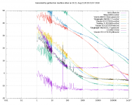
0 dB is 1nV/rt Hz, the noise of a 60 Ohm resistor at room temperature, or the input voltage noise of an AD797 or LT1028. The bottom blue line is the noise of the preamplifier, it can be ignored. -20 dB is 100 pV/rtHz, +20 dB is 10nV/rtHz.
If you follow the right arrow, there are pictures of some common regulators and references. I have presented that here on diyA already and I don't want to repeat it ad nauseam.
These are some more LEDs, and it's easy to see that they are not created equal. (attachment) The Avago HLMP-6000 is the bottom green line.
regard, Gerhard
Attachments
Last edited:
You can stamp your foot on the ground and cry "NO!" as often as you want, but that won't make it true.
Well, I did not stamp and cry (I suppose you mean shout - I never do), but I may call
for a more decent tone.
And yes, your beautiful curves are already seen before and no need to repeat them
ad nauseam - but they may be useful for this thread.
Looking at the diagram in your post, apart from the fact that coordinate labels are
missing (everybody knows it is Hz and dB), I see that the colours are displayed in
a different way on different computers and it is hard to find out which curve belongs to
which item (only indicated by a weak ink dash). It would be useful to draw lines from
the parts designations to their respective traces and put them in an order according
to the array. Two green lines seem to have the same colour.
How do these compare with your other diagrams of the same style like in post 44 of
https://www.diyaudio.com/forums/pow...tra-low-noise-vref-gled431-5.html#post5344284 and the diagrams on Flickr ?
I did not know the other diagrams, maybe Flickr is blocked on one of the computers.
Thank you for these, but it is hard to decipher the measurement conditions.
Sorry I do not own nice test equipment like this. It would be easy to repeat some
of your checks with capacitors in order to show a cap across a Zener does indeed
change nothing - at least it can do no harm to your results, isn't it ?
Tim (not Jim) Williams writes in his book "The Circuit Designer's Companion" (1991):
"<Zener> Noise is not usually a problem in voltage regulator applications since it is
many orders of magnitude below the dc zener voltage and can be virtually removed
by the addition of a parallel decoupling capacitor". I am not able to decide who is the
more respected engineer.
The perception of "Zener Noise" is apparently not consistent so I see some urge for
clarification and it would be easy to demonstrate this with your equipment.
However a comparison between different reference elements should include a
normalization with respect to their dc voltage output (but not in direct proportion),
or in other words, a higher voltage reference is allowed to have more noise. After
all a LED or other small voltage item may not be useful for the design of a hv supply.
Fair enough... or the discussion will be endless as always...DIYBras: without knowing your circuit and load, the consideration is useless.
Let me suggest back to topic noise measurements for LEDs and zener diodes.
Perhaps extra thread for zener dynamic impedance, also? Interesting to discuss.
BTW is fair to mention the referred circuit... a simple shunt regulator, with a Si PNP transistor (Siemens BSV12 if memory serves now), buffering the zener. Zener current near 10mA (68R from B to E in the transistor). No cap in parallel with zener (or test become useless). The shunt are feed with a good 100mA CCS.
On other side, there is no need to repeat my tests or explanation, or proof of that, photos, etc - in the end, if one don't believe is not a problem - is only a matter of making it's own bench tests and see for itself...
I also don't know yours fully (the reference have errors; I suppose to be similar to post #160 and not the #158). and you also measured the part inside a regulator circuit, basically the same: CCS feeding a transistor amplifying a zener string.DIYBras: without knowing your circuit and load, the consideration is useless.
Let me suggest back to topic noise measurements for LEDs and zener diodes.
And the current you applied to the diodes, is know? Base resistor, transistor beta, etc...
I measured to almost 5Hz, since my supply don't have such ripple intrusion.
Your result remember me about gas reference tubes I have measured: a little bypass is needed for supressing HF noise, due to internal impedance rise at HF. The before/after is very similar, but mechanism perhaps can differ.
Is good to clarify all points.
You refer to post 221 here, which in turn hints at post 158 in another thread and yes,
160 was correct, I myself pointed at the error in 158 schematic https://www.diyaudio.com/forums/power-supplies/164365-class-preamp-psu-16.html#post5511109.
160 was correct, I myself pointed at the error in 158 schematic https://www.diyaudio.com/forums/power-supplies/164365-class-preamp-psu-16.html#post5511109.
Well, I did not stamp and cry (I suppose you mean shout - I never do), but I may call
for a more decent tone.
OK, stamp and shout. Translations are not always bidirectional, please bear with me,
I have to think in a foreign language. Repeatedly referring to the same contentless
message is also kinda rude.
Looking at the diagram in your post, apart from the fact that coordinate labels are
missing (everybody knows it is Hz and dB), I see that the colours are displayed in
a different way on different computers and it is hard to find out which curve belongs to
which item (only indicated by a weak ink dash). It would be useful to draw lines from
the parts designations to their respective traces and put them in an order according
to the array. Two green lines seem to have the same colour.
The diagrams took a huge amount of work. They required a pre-amplifier wit 220 pV/rtHz
noise density and an Agilent 89441A vector signal analyzer. The 89441A has so many
options that have to be set up right, that you need a check list to repeat the same
measurement. So I wrote a program that controls it via the LAN; one can open port
5025 or so on 192.168.178.111 and dump GPIB commands into the port and take
results from it.
The 89441A does only FFTs over a linear frequency range; there is no
log. frequency axis. A meaningful measurement from 0.1 Hz to 1 MHz therefore
has to be decomposed into one FFT per decade, the results have to be fetched
and sorted, and from 7 decades one data set is generated. Since every decade
has a different resolution, the results have to be corrected for noise bandwidth.
The data set then is plotted by gnuplot; my program generates a gnuplot program
to do that and it automagically calls Gnuplot to display the results. It also generates
.png and embedded postscript files for publication.
I couldn't care less that the colors repeat after 8 or 10 traces. If you are a Gnuplot guru,
I'm open to suggestions. There is a myriad of options.
How do these compare with your other diagrams of the same style like in post 44 of
https://www.diyaudio.com/forums/pow...tra-low-noise-vref-gled431-5.html#post5344284 and the diagrams on Flickr ?
They are essentially the same. But the input capacitor of the low noise preamplifier
was much too small, so that it's 1/f region was not 1/f but 1/f**2, a fact that Scott
Wurcer saw on the spot. The 24 10uF foil capacitors have been replaced by
a 4700 uF/25V wet slug tantalum, and the 1/f region now looks OK. There could be
more of them, but at a price of €100/pc., I'm reluctant to improve that for lower frequencies.
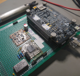
Also, the Agilent 89441A has quite poor 1/f behavior; I'm trying to cure this with
a module made from an LT2500-32, a BeagleBoneBlack and a few CPLDs, but as soon
as I try to read/write the SPI interface, I get a bus error. That is a large software
problem; the hardware is easy, see the picture.
I did not know the other diagrams, maybe Flickr is blocked on one of the computers.
Thank you for these, but it is hard to decipher the measurement conditions.
Sorry I do not own nice test equipment like this. It would be easy to repeat some
of your checks with capacitors in order to show a cap across a Zener does indeed
change nothing - at least it can do no harm to your results, isn't it ?
A customer of mine suppresses flickr because of a blacklist; his workers are
not supposed to watch pics, not even technical ones. I only recently learned that
flickr adds advertisements every 5th picture. I have a good add blocker.
[measurements with additional par. cap] Yes, but my very first priority is to get the LTC2500-32 working; sooner or later I'll do a write-up.
Tim (not Jim) Williams writes in his book "The Circuit Designer's Companion" (1991):
"<Zener> Noise is not usually a problem in voltage regulator applications since it is
many orders of magnitude below the dc zener voltage and can be virtually removed
by the addition of a parallel decoupling capacitor". I am not able to decide who is the
more respected engineer.
I don't care too much. There is no point to try to prove / disprove Ohm and Kirchhoff.
Also, I can't remember to disagree with Jim Williams.
However a comparison between different reference elements should include a
normalization with respect to their dc voltage output (but not in direct proportion),
or in other words, a higher voltage reference is allowed to have more noise. After
all a LED or other small voltage item may not be useful for the design of a hv supply.
I have given the resulting output voltages usually. Making the measurements and
providing the data does not put the load on me to chew them thru or to formulate
opinions.
Please do not forget that noise adds up geometrically. The output voltage for 16 LEDs
is 16 times the LED voltage drop. The noise voltage is only 4 times the noise of one diode.
BTW you may encounter funny effects with a OA150 tube and a parallel capacitor,
in that it forms a saw tooth oscillator.
regards, Gerhard
Attachments
Last edited:
- Home
- Design & Build
- Parts
- Some noise measurements for LEDs and zener diodes