I will say if you're using a Toroidy 300va tranny in the 4U chassis, it will get very tight laying it horizontally.
I used a 500VA in all my 4U builds, transformer horizontal center nearest front panel, plenty of room for me, dual mono not so much. My F5 has dual 300VA, home built case is more 5U size.
Russellc
I used a 500VA in all my 4U builds, transformer horizontal center nearest front panel, plenty of room for me, dual mono not so much. My F5 has dual 300VA, home built case is more 5U size.
Russellc
Those Audio Supreme encapsulated transformers from Toroidy are oversized big! I think mine is 6" in diameter, the baseplate is about 12" deep and the universal PSU board is about 7" before breaking off the diode section. It makes for a tight fitting section
Those Audio Supreme encapsulated transformers from Toroidy are oversized big! I think mine is 6" in diameter, the baseplate is about 12" deep and the universal PSU board is about 7" before breaking off the diode section. It makes for a tight fitting section
5U has much more room, My BA3 is in one, but only by default as I had purchased it originally for F5 Turbo build. The extra cooling of the larger heat sinks may also pay dividends in longer cap life in the power supply... now that may favorite Panasonics are no longer available.
Russellc
5U has much more room, My BA3 is in one, but only by default as I had purchased it originally for F5 Turbo build. The extra cooling of the larger heat sinks may also pay dividends in longer cap life in the power supply... now that may favorite Panasonics are no longer available.
Russellc
Whenever I start building another SS amp I most definitely will be using a 5U chassis. I have almost all the parts for a mono BA3
Fugly!
")
Thanks ZM !
I bought the front plate and top plate from Modushop.
The perforated bottom plate and the back plate I ordered cut to my specs from a German supplier (www.prokilo.de). That's also where I got the 10x10 mm square aluminium rods that I cut to length myself.
All the drilling and tapping courtesy of me
Hand-tapping can have a somewhat meditative side to it ...Only challenge are the large holes for the front panel power switch or the XLR connectors on the back, and the IEC inlet. Careful work is required there.
The front plate is actually mounted off-center, shifted downward a bit. In that way, it forms something like a "skirt", so that the tall feet (that are good for ventilation) don't show. More harmonious proportions that way in my opinion
Best regards,
Claas
Attachments
Last edited:
well , I'm permanently floating

Yes, of course! I picture you as being able to levitate at will and move small objects such as SITs using the power of the DIY FORCE.


So I bought a whole new set of circuit boards, matched pair of 2SJ4s, parts, and the Aleph J transistor kit. And I assemble everything, using a anti-static wristband (that yes, was grounded) when mounting the FETs.
Same result - no bias voltage and too much DC (20VDC) on the output.
Out of frustration, I swapped the working side with the bad side, swapping circuit boards and connections. Somehow I missed putting the positive power supply lead on. Power up for a second, realize my mistake when the blue LED doesn't light up. Fix that problem. And now get -5VDC on the "good" PCB output.
I'm throwing in the towel. Can't afford to be throwing $40 at matched pairs of 2SJ4s, which apparently even more sensitive than C3m pentodes, which like to break their filaments if you look at them wrong.
well, if you have permanent Gremlins , try finding nearest Greedy Boy.... with more mileage in electronics , to help you in exterminating Gremlins
JFets check is easy - with simple matching jig (all you need is DMM and 9V battery)
mosfets - if there is no short between pins , they're most likely functional
so , find nearest fella , open dedicated thread if needed , and bloody amp must sing
if and when you check input JFets , if some is Dodo and you have no spares , buzz me and I'll send you two pairs of matched J271 (no money involved) ...... pretty much same thing , when Aleph J is in question
Last edited:
Hi kstagger,
Really sorry you're having so much trouble. I second what ZM has said.
For testing the jfets, once you have them unsoldered, you can use
the P-channel setup shown here:
Transistor matching
You can also replace the amp meter with a small value resistor
(say anything from 10 to 100 ohm) and back out the current value.
That should tell you if your jfets are ok.
I hope you're able to get this fixed.
Cheers,
Dennis
Thanks everyone - I took a breather and got back at. Looks like I was really easy on the soldering iron when putting the 2SJ74s in. Everything seems to be good now...
Struggling with finding a stable bias point as the amps heat up. Wish I had a second DMM so I could adjust both at the same time.
One side I can get the DC/offset on the speaker jacks down to almost 0mV. But the other side - with the Ebay punkydawg 2SJ4s - I can only get down to 110mV (cold) or 200mvish (hot). Then I run out of pot travel. Something to worry about or close enough for government work?
btw- for future builders, I blame a lot of my problems on my shoddy PCB soldering work. I've done most of my DIY-ing in point-to-point world. Don't think I've been applying enough heat, and need to do a better job cleaning up flux, etc.
Last edited:
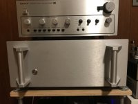
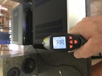
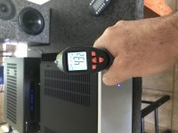
Build complete and sounds wonderful. Interesting that the temperature is lower on the left channel, should I recheck bias again after running it for an hour or two? I initially set bias then again after 30mins. First amp project and already thinking about building another one for my son!
Attachments
- Home
- Amplifiers
- Pass Labs
- Aleph J illustrated build guide