SMPS response time
Hi i checked the response time - setup time at LRS150-24
looks not ideal...FF propose faster than 10ms =step response
...in the datasheet:
Output: SETUP 500ms
Rise Time 30ms @230VAC input
Hold up time: 40ms @230VAC
LRS 350-36
hold up time 16ms @230VAC
...so FauxFrench you have a task:
Design a better SMPS

reset= mute switch..
Hi Emilvv
you ask about the reset--> mute switch of this YJ TPA3255 board:
here in the developer thread you will find: post 679 page 68.
TPA3255 - all about DIY, Discussion, Design etc.
my proposal is to read all the pages...yes its hard but you will learn a lot!
chris
Hi Emilvv
you ask about the reset--> mute switch of this YJ TPA3255 board:
here in the developer thread you will find: post 679 page 68.
TPA3255 - all about DIY, Discussion, Design etc.
my proposal is to read all the pages...yes its hard but you will learn a lot!
chris
Attachments
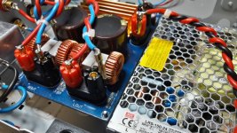
if you want to save money for the ouput coils?
i used the other coils (board 2,3,)
setup is 4 ohms output impedance.
the original are 13µH-12,4µH.
i measured from all the highest = near 13µH to use it for parallel the coils--> finnaly i get 6,3µH. at the TI output designer i found the 680nF as best.
sound session hopefully tomorrow.
chris
i used the other coils (board 2,3,)
setup is 4 ohms output impedance.
the original are 13µH-12,4µH.
i measured from all the highest = near 13µH to use it for parallel the coils--> finnaly i get 6,3µH. at the TI output designer i found the 680nF as best.
sound session hopefully tomorrow.
chris
Attachments
if you want to save money for the ouput coils?
i used the other coils (board 2,3,)
setup is 4 ohms output impedance.
the original are 13µH-12,4µH.
i measured from all the highest = near 13µH to use it for parallel the coils--> finnaly i get 6,3µH. at the TI output designer i found the 680nF as best.
sound session hopefully tomorrow.
chris
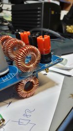
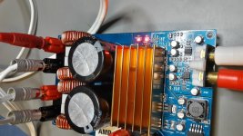
Hi .....nice rainy Sunday...
i checked the SQ of this cheap coils paralleling. its really a nice sound. i try the 1µF on the output but i really prefer the combination 6,3µH and the 680nF caps on the output filter. finally the SQ is not as good as the shielded coils.
shielded coils sound darker and more dynamic, around the voices and instrument less noise and stable position.
chris
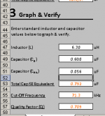
The TI's design is common mode is because it's meant to test out multiple load. Example 2 ohm, 3 ohm, 4 ohm, 6 ohm and 8 ohm. Once you narrow down to the driver you are using, you can specifically tune to your liking.
For me I will use the hybrid to get closest to 0.707 with my 3 ohm driver.
For me I will use the hybrid to get closest to 0.707 with my 3 ohm driver.
The TI's design is common mode is because it's meant to test out multiple load. Example 2 ohm, 3 ohm, 4 ohm, 6 ohm and 8 ohm. Once you narrow down to the driver you are using, you can specifically tune to your liking.
For me I will use the hybrid to get closest to 0.707 with my 3 ohm driver.
thanks for your explanation..i will try at home...in the office the TI designer blocked
which type of cap...wima?
chris
thanks for your explanation..i will try at home...in the office the TI designer blocked
which type of cap...wima?
chris
Film or Mylar rated 63V or more.
...amp light next step...
hi
sorry but actually i have not enough time for audio...but i try to proceed with my
"AMP light"
i did the cabeling. i still keep the idea that i want to change the tpa boards so i kee the big connectors. to go ahead with my "favorite" board i need more time for comparing some ideas...no time now
until the 28th of September i have to !.....= introduction of my amp to friends
any other suggestion if experts look at the pics?
thanks
chris
Attachments
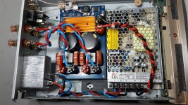
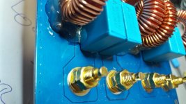
It's generally recommended to have a short-as-possible thick wire from the chassis to the safety earth terminal of your IEC. Also, does that IEC have a fuse? If not, I would recommend having a fuse on your mains live wire. (These are just suggestions for safety.)
Just curious: for the internal wiring of the speaker out and DC in, looks like you soldered banana plugs to your wires. Aren't those screw terminals where you could just put the wire into the terminal directly, and screw it down? I doubt it makes a difference either way, but given a choice, I usually opt for the least-effort approach.
Just curious: for the internal wiring of the speaker out and DC in, looks like you soldered banana plugs to your wires. Aren't those screw terminals where you could just put the wire into the terminal directly, and screw it down? I doubt it makes a difference either way, but given a choice, I usually opt for the least-effort approach.
It's generally recommended to have a short-as-possible thick wire from the chassis to the safety earth terminal of your IEC. Also, does that IEC have a fuse? If not, I would recommend having a fuse on your mains live wire. (These are just suggestions for safety.)
Just curious: for the internal wiring of the speaker out and DC in, looks like you soldered banana plugs to your wires. Aren't those screw terminals where you could just put the wire into the terminal directly, and screw it down? I doubt it makes a difference either way, but given a choice, I usually opt for the least-effort approach.
Thanks matt for your input.
the power switch had a fuse included:
https://www.diyaudio.com/forums/class-d/309813-wrong-tpa3255-33.html#post5526726
the bananas are the second best solution because i am still want to try some changes (SQ) on my different boards.
the earth connection is a very good idea...thanks
Last edited:
....noise after changing new opamp..
Hi
i want to to my last step for mod for the YJTPA3255 boards. it was planned to compare a new opamp vs the original ST Tl072. the late night session was not successfully. desoldering was not a topic but after a break I i put the AD8599 otherway round in. and switch on..so i guess this opamps are dead.
be aware that the labeling on the PCB is not correct !!
after this bad i start to desolder the AD8599 and but new in. on the left channel is a realy loud noise floor.
i cheked according to Faux French amazing hint:
A proposal to check if it is the power amplifier itself that causes the noise or an OPAMP: Use a test speaker, for hearing noise you do not need your good speakers.
An 8 Ohm dummy load connected to the two (normal) speaker terminals of the flawed channel. A speaker (8 Ohm) connected to only one of the speaker terminals, the other end of the speaker being connected to '+" on a 1000uF or 2200uF capacitor. The negative terminal (-) of the capacitor being connected to amplifier ground. No signal at the input.
The normal output is two amplifiers operating in counter-phase. What we would like to know is if it is only one of the two amplifiers that introduces the noise.
If only one of the two amplifiers of the noisy channel has noise, it is unlikely the noise is introduced by an OPAMP. We can then concentrate on the power amplifier itself. If both speaker terminals have noise, it is likely the noise comes from the amplifier input with an OPAMP as the source.
i got on the left channle on both terminals +plus and - negativ a loud noise floor. right channel is ok.
ideas?
thanks for your help
Hi
i want to to my last step for mod for the YJTPA3255 boards. it was planned to compare a new opamp vs the original ST Tl072. the late night session was not successfully. desoldering was not a topic but after a break I i put the AD8599 otherway round in.
and switch on..so i guess this opamps are dead.be aware that the labeling on the PCB is not correct !!
after this bad i start to desolder the AD8599 and but new in. on the left channel is a realy loud noise floor.
i cheked according to Faux French amazing
hint:A proposal to check if it is the power amplifier itself that causes the noise or an OPAMP: Use a test speaker, for hearing noise you do not need your good speakers.
An 8 Ohm dummy load connected to the two (normal) speaker terminals of the flawed channel. A speaker (8 Ohm) connected to only one of the speaker terminals, the other end of the speaker being connected to '+" on a 1000uF or 2200uF capacitor. The negative terminal (-) of the capacitor being connected to amplifier ground. No signal at the input.
The normal output is two amplifiers operating in counter-phase. What we would like to know is if it is only one of the two amplifiers that introduces the noise.
If only one of the two amplifiers of the noisy channel has noise, it is unlikely the noise is introduced by an OPAMP. We can then concentrate on the power amplifier itself. If both speaker terminals have noise, it is likely the noise comes from the amplifier input with an OPAMP as the source.
i got on the left channle on both terminals +plus and - negativ a loud noise floor. right channel is ok.
ideas?
thanks for your help
...labeling opamp
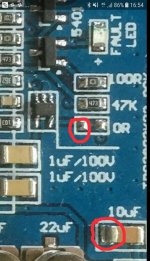
to be clear about the opamps label:
on the pic you see the labeling of the opamp. so if you looking from left side you can read the label first row TL072, 2nd row ST xxx.
under the chip is readable from right ! - that when i made my bad.(pic will come)
to be clear about the opamps label:
on the pic you see the labeling of the opamp. so if you looking from left side you can read the label first row TL072, 2nd row ST xxx.
under the chip is readable from right ! - that when i made my bad.(pic will come)
Attachments
- Home
- Amplifiers
- Class D
- What is wrong with TPA3255?