@penatjazz, Regarding su5, agree with you about the small hole in the front panel. After I was able to look at it more closely it was clear there is in fact a optical receiver back there. More generally with regard to su5, I hope you know that although I am personally not highly motivated to make su5 into something with better sound quality, I would be happy to help you do it if you want to.
That being said, still seems like it should be easier to mod one of the usual Q2M boards we mod here into something good with remote control capability. Also, don't know if you are aware but some people are starting to play around with running our usual ES9038Q2M boards from an RPi instead of an Arduino. That would actually be a good way to go if one wanted streaming wireless, wireless control from a phone or another computer, etc. The dac itself could be hidden away with the rest of the stereo equipment.
In other words, some people are working on or have already connected up one of our typical Q2M boards to work with RPi much like Allo Katana does. They are able to do that because somebody wrote a native ES9038Q2M sound driver for RPi.
While here talking about various options (if it is okay for me to ramble on a little), some readers may be aware when I modded my own Q2M dac I kind of took a shortcut with the differential summing part of the output stage. I had some very tight tolerance 10k thin film resistors in stock and used those rather than ordering parts and waiting to get everything to make the output stage into a more complete analog filter to clean up and attenuate whatever little remaining HF/RF junk may have come out of the dac. Of course, I suggested to everyone else that they do as I say and not as I do, and that they should probably use the ESS recommended differential summing circuit which includes proper filtering.
With regard to that analog filtering, there is more than one way to select component values for the filter. Usually, the resistor and capacitor values are chosen to produce a filter shape that is gaussian or bessel, something like that, with a very slow and gentle roll off in frequency response, but minimal rate of change of phase response as a function of frequency. The rate of change of phase with respect to frequency is also known as 'group delay.' The thing about it is that if phase changes fast as frequency changes it can sound audibly objectionable, depending.
However, as always there is a design trade off. If we roll off the frequency response slowly in order to minimize audible group delay, there could be more undesirable frequencies leaking through the filter. To put it another way, the frequencies we want to get rid of might not be sufficiently attenuated. Because the analog output filter is composed of multiple resistors and capacitors, their values could be chosen to more quickly roll off or attenuate undesirable HF, but at the cost of potentially making group delay effects more audibly objectionable. So, someone has to figure out what the best balance is, or maybe even if adding additional filtering stages would be helpful.
This brings us back around to being prepared to talk about the latest changes we think may be going on with Allo Katana development. It could be they are looking at trying to see if the analog filtering in the output stage is optimized as much as possible. From what they say it sounds like they originally designed the filter as ESS recommends assuming that would be the best choice. Apparently, they are finding that it can sound a little better with some adjustment to filter type and cutoff frequency. And, with any really high performance dac everything little thing matters, including details of the analog filter.
Power supplies are another matter, too. Maybe more about that later. In the meantime I did post a personal opinion in another thread about that: http://www.diyaudio.com/forums/vendor-s-bazaar/294940-fifo-buffer-rpi-sbcs-222.html#post5512454
thanks for all the notes, I will keep them in mind as usual for a future plan. At the time being I will not do any hard modifications, as a matter of fact I get decent sound (for my personal taste/system/room) with an additional tube buffer and some pc software related tweaks. So the only move I could do for now is to try a cheap universal apple remote, or copy the related codes to a "learning" usb remote and test them.
Apple Remote | H i F i D U I N O
apple remote | eBay
Apple Remote | H i F i D U I N O
apple remote | eBay
Last edited:
@Markw4
Link ??
They are able to do that because somebody wrote a native ES9038Q2M sound driver for RPi.
Link ??
@Markw4
Link ??
Well, could be I misspoke on that a little. People have hooked up a Q2M to the RPi I2S bus and sent audio out to it that way, maybe including you? (maybe using the ES9018 driver?). I think people have also hooked up RPi I2C bus so as to be able to access Q2M registers at the same time so it can be poked into whatever configuration is desired using an I2C app. So, although I believe something can at least be hacked together to make Q2M play using RPi as desired, it may not be seamless yet. Given that there seems to be a Q2M data sheet out there somewhere that some people have gotten without going through NDA, don't see any reason why it could't be completed at any time, unless of course ESS puts it's corporate foot down and objects. Would that be a more accurate description of the current status?
EDIT: Actually, this looks like eslei what was working on when he decided he needed an I2C bus logic analyzer?
Last edited:
I can confirm that the "apple remote" code work ok with su5. I have managed to set an "apple tv" preset on a USB remote control from its software database. The codes are there but they are hidden, I do not have an IR decoder. But it simply works.
MENU.... changes ESS filters
Left/Right .... Sources selection
Up/Down ..... DAC volume
OK ... mute/un-mute
MENU.... changes ESS filters
Left/Right .... Sources selection
Up/Down ..... DAC volume
OK ... mute/un-mute
Last edited:
The AMB gamma 2, which uses the Wolfson (now Cirrus I think) WM8741/42, has an integrated SRC4192, which is an earlier version of one of the SRC chips that MarK has been working with. I also think that it was also part of the reason that the Gamma 2 sounded so good. It was a giant killer in it's time, before the ESS chips became so prevalent. I also expect that the latest AK chips work very well with the 4137, since they were designed by the same company
I didn't try this board, but I tried 3 different more expensive Chinese Sable boards after reading DIYAUDIO's thread. All of them sounds bad compared to the well known brand's DAC based on ESS, WM8741 or AKM. I know ESS can sound really great in professional designed DACs, but implementation would not be easy. Those who design commercial DAC know MHz range electron behavior. Board layout, parts, everything seems to matter. My impression is, the guy (or girl) who designed this board does not have enough knowledge designing digital section of DAC board, sorry.
Analog section of the cheap commercial DAC is usually horribly cheaply made, so I think buying a reputable commercial DAC and do some mod to the analog section would be more reasonable for DIYers. Black Lion Audio does this business for more than 10 years, BTW.
..., so I think buying a reputable commercial DAC and do some mod to the analog section would be more reasonable for DIYers.
That might be true if the main thing wrong with a commercial dac built to a price point was that the analog section was lacking. Usually, that doesn't seem to be the case. The very best dacs virtually don't cut corners anywhere, but those built to a price point seem to cut corners pretty much everywhere equally, not just the analog section.
If you look at one of the very cheap $39 Chinese ES9038Q2M dacs discussed in this thread, pretty much everything is bad, but at least they have a ground plane, and they can be modded incrementally to fix as many areas as one would like.
In this thread so far, there are example of how to fix almost everything, if one wanted to do it all. The only thing really missing is what most commercial dacs miss, an outboard custom digital reconstruction filter. We haven't figured out how to do that, but virtually no commercial dacs go that far towards implementing perfection in terms of what a Sabre dac can be at it's best.
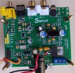
The latest version (VR 1.06 or 1.07) of the ES9038Q2M discussed on this thread, if come with the TFT display, support the Apple Remote as below.this su5 unit has a remote, so this "black hole" on the front is a sensor for this.
So, if this remote looks like the same with the other boards, there might be a chance that there are some additional functions there like filter selection etc. Go figure!
Anyway if someone has this remote and can decode its infrared commands, maybe those could be shared here.
NEW SU5 ES9038Q2M DAC HIFI XU208 DSD TPA6120 Headphone audio Amp Bluetooth 5.0-in Digital-to-Analog Converter from Consumer Electronics on Aliexpress.com | Alibaba Group
but... this one says that it supports "apple remote", I do not know what this is supposed to mean.
ES9038 ES9038Q2M DAC Decoder board Support IIS DSD DOP 384KHz with Amanero USB-in Amplifier from Consumer Electronics on Aliexpress.com | Alibaba Group
So it might be the same.


The SU5 DAC seems to be the same. Markw4 can verify that.
The latest version (VR 1.06 or 1.07) of the ES9038Q2M discussed on this thread, if come with the TFT display, support the Apple Remote as below.
View attachment 696740 View attachment 696741
The SU5 DAC seems to be the same. Markw4 can verify that.
It works exactly this way. A programmable remote controller will control all of them by selecting something like "apple tv" in the devices/presets database.
Decided to see if I could get a little more sound quality improvement for my modded Chinese DAC. I think it has helped get it a little closer to DAC-3. Probably will have a little more to say about that after I have a chance to listen to it for a few more days.
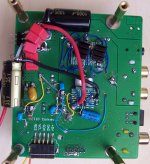
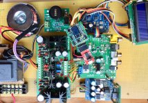
What I did was change the way power is routed to AVCC supply opamp. It was the last opamp from the incoming power connection, at the far end of the power distribution traces. While I was rerouting power to it, I also changed the AVCC 3.3v opamp input source voltage from a dedicated 3.3v regulator to a high performance 3.3v LTC6655 reference. That left me with an unused 3.3v regulator so I decided to use it for dedicated VCCA power.
Pictures available below showing current status of mods to the dac and the present test setup. Please note that the dac board is actually getting 5v power from a an external supply rather than the on-board 5v regulator. The output pin of the on-board regulator has been lifted. The lifted pin is indicated in one of the pictures with a red circle.
Attachments
Last edited:
SPDIF still works, although the resistor has been moved and there is a jumper soldered across the pads where it was located before. Reason is the SPDIF input connects through one of the two ES9038Q2M GPIO pins. The GPIO pins among other things can be set to output the MCLK signal, the internal master clock derived from the 100MHz hardware clock on the dac board.
One reason to output MCLK would be to use it as the master clock for an external I2S device. That way the I2S bus could be run in master mode with the Q2M supplying all the clock signals and the external device only supplying the DATA signal.
I was thinking about letting Q2M clock an SRC4392 board with Q2M as master and SRC4392 as slave, just as an experiment in trying master mode. Never got around to doing everything I would need to make it work, but in principle it could be done.
Since an SRC4392 has a maximum master clock frequency of 30MHz, I would need to use the internal Q2M MCLK divider to reduce its external 100MHz Xi clock to an internal MCLK clock frequency of 25MHz. Then both Q2M and SRC4392 would be clocked at 25MHz which would be fast enough to try it out, although would it would not support some of the highest sample rates that way.
It also would have been possible to use the GPIO pin normally used for TOSLINK input to output MCLK instead of using the SPDIF pin, but there were nice pads there where the resistor was mounted which could be used for soldering on a MCLK terminal to send off to SRC4392.
Last edited:
- Home
- Source & Line
- Digital Line Level
- ES9038Q2M Board