It seems like you could run both channels on the same heat sink, don't you think?
Yes, if you are building a single chassis MoFo, both channels positioned just right will fit on one Dell FD841 cpu cooler. That might not work with aftermarket cpu coolers as the mounting pads are smaller than the Dell’s.
Both channels on a single Dell would significantly reduce cost and weight.
Last edited:

You have to make sure that the cooler is capable of dissipating the wattage generated by the MOSFETs. The link shows that cooler is just a small heat sink with no heat pipe technology. I doubt that would be good for this application.
I don't know how they compare, but this exact model, or at least the original intel one BXSTS100P is rated for 95W dissipation look at the thermal solution table. AFAIK Xeon's maximum recommended CPU temperature is 74C. IDK what is the maximum recommended for the Mosfets though. Moreover, although some Xeons use a passive heatsink there are case fans moving the air around it anyway so de-rating if using in totally passive arrangement is of course needed. I just don't know how to calculate it.
Last edited:
Wattage is not enough information, though. Without the maximum allowable temperature for the mosfet it is actually useless. If you want to keep it at 40C in a 24C room it would take a much bigger heat sink than if you could go up to 60C for example... As I don't believe anybody is willing to do the math, experimentation is the way to go though! lol
Looking at the data sheet, the Mosfet operating range is up to 175C, but the drain-to-source-on-resistance (whatever-that-is) goes up with temperature. I assume that at some point well below 175C this increased resistance causes problems.
Looking at the data sheet, the Mosfet operating range is up to 175C, but the drain-to-source-on-resistance (whatever-that-is) goes up with temperature. I assume that at some point well below 175C this increased resistance causes problems.
Last edited:
Hi
I like that model where you can mount the pcb directly on the heatsink but have no clue about possible heat dissipation.
24V DC Fan Cooling Set with Metal Grill 100mm Aluminum Heat Sink and Thermostat | eBay
Any idea ?
I like that model where you can mount the pcb directly on the heatsink but have no clue about possible heat dissipation.
24V DC Fan Cooling Set with Metal Grill 100mm Aluminum Heat Sink and Thermostat | eBay
Any idea ?
Hi
I like that model where you can mount the pcb directly on the heatsink but have no clue about possible heat dissipation.
24V DC Fan Cooling Set with Metal Grill 100mm Aluminum Heat Sink and Thermostat | eBay
Any idea ?
This idea is very good, but I don't think the thermostat is a very good one. I know not much about electronics but I believe Bias adjustment is directly dependent on the temperature of the gain element.
On a passive radiator when the temperature reaches equilibrium it won't vary much at all (although it is influenced by the room temperature). Keeping the bias constant. And I believe that's why bias adjustment ismade with the chassis closed and amp warming for an hour or so.
On an active radiator there is the problem of temperature fluctuation. The thermostat of the link shows a temp fluctuation of 15C (sets off at 65C resets at 50C). If the bias is sensitive in the region it will be fluctuating as well. Whether that is a problem or not I'll leave to others.
I believe a better solution would be to scrap this thermostat and install a PWM that has a much narrower temperature range and controls the fan at low levels instead of all or nothing like the thermostat.
...Looking at the data sheet, the Mosfet operating range is up to 175C, but the drain-to-source-on-resistance (whatever-that-is) goes up with temperature. I assume that at some point well below 175C this increased resistance causes problems.
For a linear audio amp, this resistance should be "much less" than load resistance. So much less than 8r. 0.8r would be fine, with a small loss of maximum power. 0.4r is even less.
Re-normalizing to 0.075r @ 25C, and extrapolating the plot past "hot!", we predict that Rds(on) will just start to annoy us above 300 deg C. However well before that the epoxy seals have cracked and let air-damp into the crystal which is early death.
That's not a problem.
There can be a bias problem. The adjacent plot can give gate voltage for an assumed current. In this case something like 2 Amps. A bogie device wants 4.7V to give 2 Amps. This will vary with device, but say we set whatever it wants for 2 Amps while at 25C. Now let it warm to 175C. It wants 3.9V to hold 2 Amps. If we continue to apply 4.7V we will get about 7 Amps. An unhappy amplifier and owner. Michael's resistive choke adds a trace of stability but not a lot.
Attachments
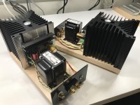
I appreciate all the creativity with microwave transformers, computer heat sinks, etc. and I enjoy those efforts. But please understand that if you're going to experiment, your mileage may vary. I presented something that works reliably, so that's my preferred implementation. Plus, it saves me emails. ")
I appreciate all the creativity with microwave transformers, computer heat sinks, etc. and I enjoy those efforts. But please understand that if you're going to experiment, your mileage may vary. I presented something that works reliably, so that's my preferred implementation. Plus, it saves me emails.
Michael,
Plus, those awesome Aavid sinks that you chose and BB are much more afordable then a chassis! That design just looks cool!
Greg
The "bracket" that is mounted over the mosfet is that a kind of "standard" equipment? ….does it press the mosfet against the heatsink so no screw is needed to fasten the mosfet to the heatsink or what is the purpose?
My intention was to make a M3 thread in the heatsink for the mosfet but I would like to learn about the other "solution"...…..
My intention was to make a M3 thread in the heatsink for the mosfet but I would like to learn about the other "solution"...…..
Attachments
Ok....I have the 20 cm in height version of the heatsink. So I will make a M3 thread in the middle…….should be the best place to have the most even heat dissipation. A heatsink that large it should be ok just to place it on the board without lifting it a bit to have better air circulation. But that is some small details I have play with later when the project is that far...…I may lift it a cm or so.
The "bracket" that is mounted over the mosfet is that a kind of "standard" equipment? ….does it press the mosfet against the heatsink so no screw is needed to fasten the mosfet to the heatsink or what is the purpose?
My intention was to make a M3 thread in the heatsink for the mosfet but I would like to learn about the other "solution"...…..
That "bracket" looks like a simple, anodized, extruded section of channel.
Ok.....I was just interested in learning if this was a standard way of mounting these devices and also if is was done without a screw in the mosfet so is was a kind of spring load to force the mosfet to the heatsink. Maybe to avoid drilling a hole in the heatsink so it can later be used for other projects.
- Home
- Amplifiers
- Pass Labs
- Build This MoFo!