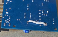
I've been examining the board and I think I've worked out where the trace that leads to the unsoldered positive pin on the replaced cap comes from:
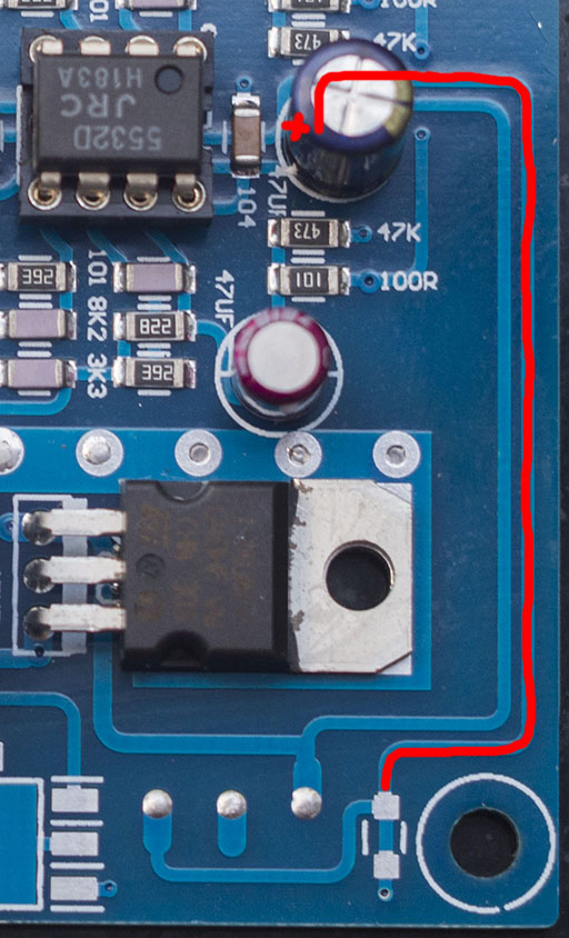
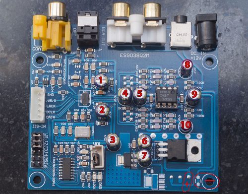
So to fix this, I should run a jumper cable from the positive pin on the cap to the solder pad at the bottom right of the board?
So to fix this, I should run a jumper cable from the positive pin on the cap to the solder pad at the bottom right of the board?
Attachments

I managed to get my CD card reader working so here's some pictures of the damaged I did and my proposed repair:
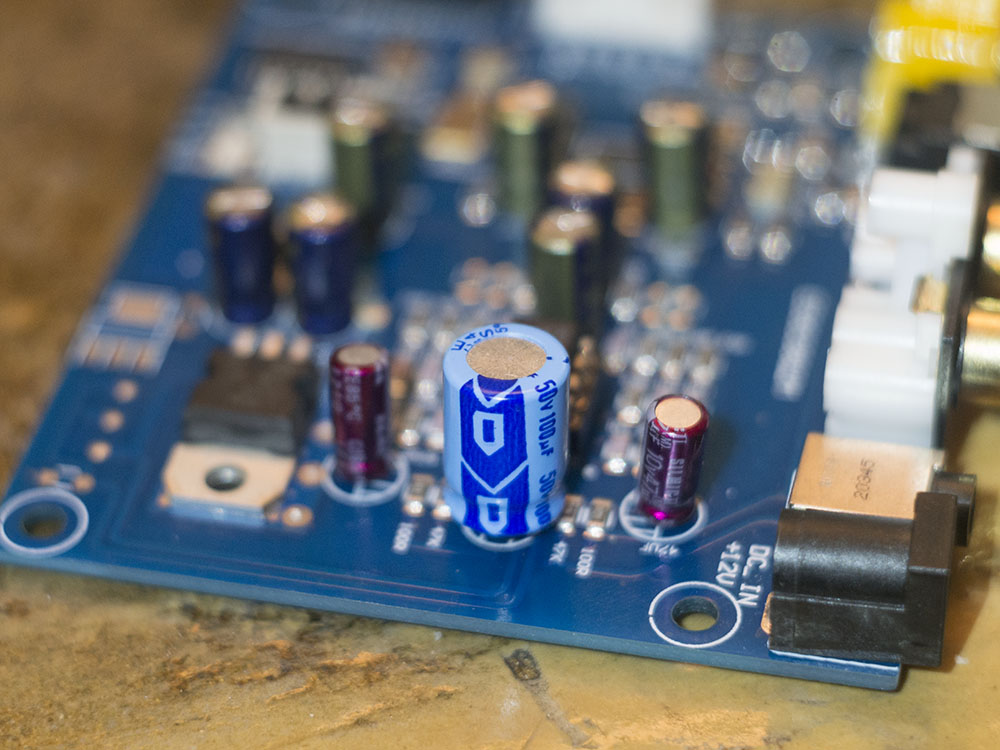
The replacement Rubycon 100uF 50V cap:
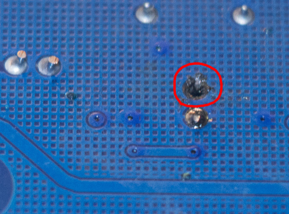
The missing solder pad on the underside of the board on the positive pin of the Rubycon:
How I propose to run a jumper cable to repair the board, I haven't soldered it in place yet:

The replacement Rubycon 100uF 50V cap:
The missing solder pad on the underside of the board on the positive pin of the Rubycon:
How I propose to run a jumper cable to repair the board, I haven't soldered it in place yet:
Attachments


Last edited:
I tried my board out, powering it with a 13v 200mA wall wart ...
and what kind of sound are you expecting?
and what kind of sound are you expecting?
Even with a wall wart, nothing so bad, if you could hear it I'm sure you'd agree there is something wrong.
Maybe I can make a recording of the board playing music so you can hear how bad it is.
don't you think that part of the naked wire is touching the ground plane?
I don't understand what you mean, you'll have to be more specific.
The end at the cap isn't touching anything other than the pin of the cap, the other end isn't touching anything yet as I haven't soldered it in place.
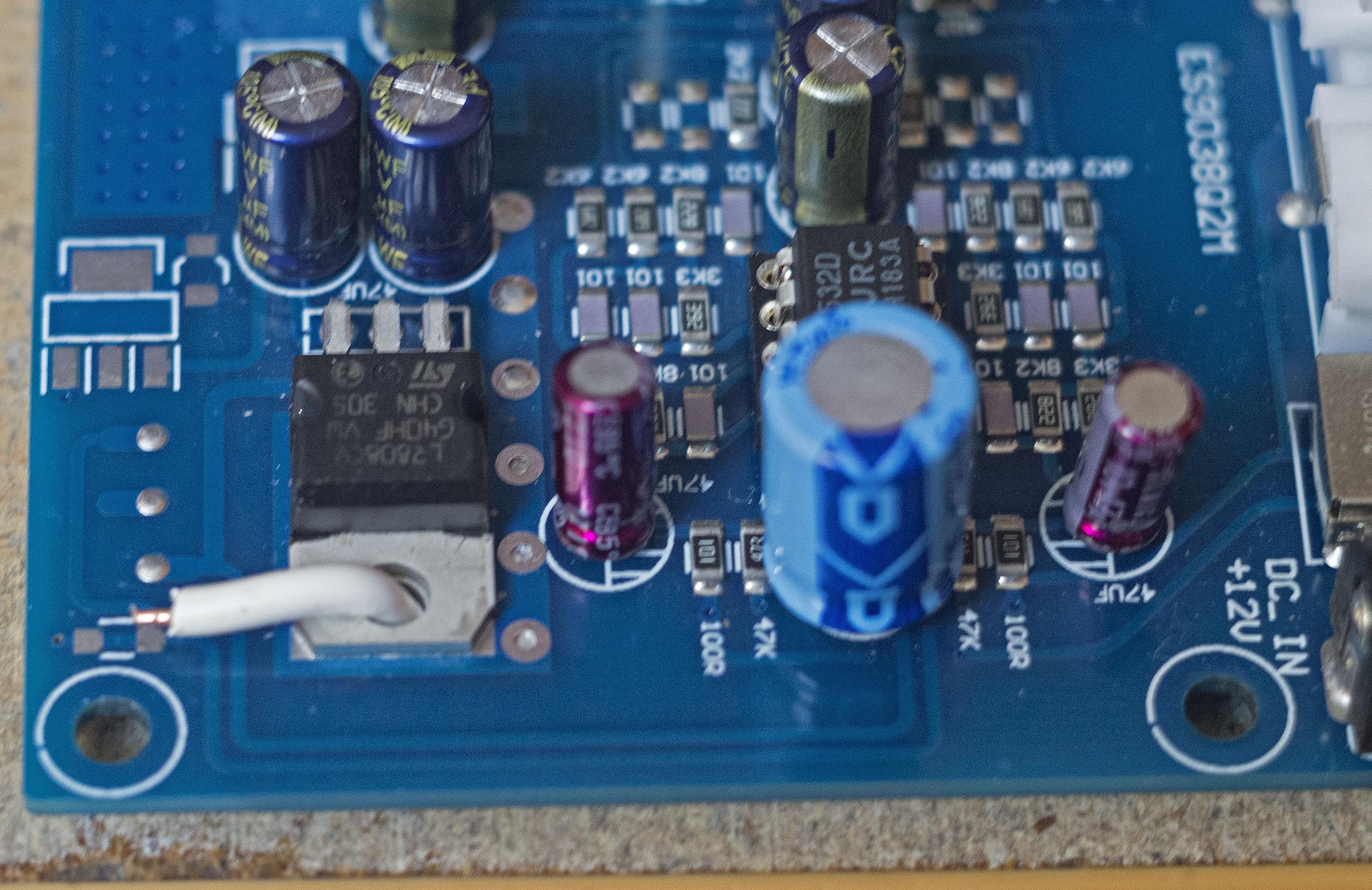
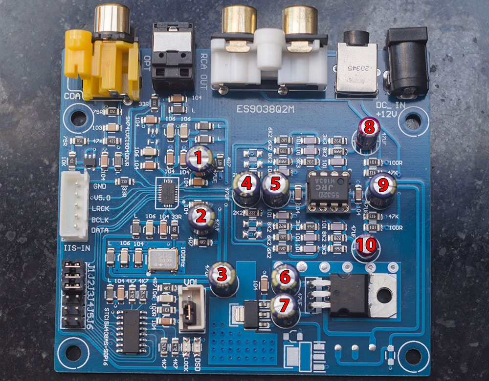
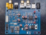
After the mess I made replacing one cap, I'm reticent to change the others, so I thought I'd ask which of the ten caps on the board are in the signal path and need to be replaced; hence I've labelled the caps 1-10. 9 is the one I've already replaced. So, which ones need to be replaced?
Attachments
i would suggest you to take a look at this:
ES9038Q2M Board
OK, I am sorry to say but all this cap change is pretty pointless. the best you can do is to read the whole thread from the beginning and try to understand what the mods suggested mean.
ES9038Q2M Board
OK, I am sorry to say but all this cap change is pretty pointless. the best you can do is to read the whole thread from the beginning and try to understand what the mods suggested mean.
Last edited:
Are you suggesting that cutting the trace connecting the negative line to the ground would improve the SQ, even when using the board with a wall wart plugged into the barrel connector?
My understanding is that that trace shouldn't be cut until I run the board from a dual rail supply and as Mark wrote:
So right now, while running the board from a single 12v supply, that trace connecting to the ground is needed and I won't cut it until I have built a dual rail linear regulated PSU to power the board.
My understanding is that that trace shouldn't be cut until I run the board from a dual rail supply and as Mark wrote:
it connects the negative rail to ground which would be needed if using a single +12v supply.
So right now, while running the board from a single 12v supply, that trace connecting to the ground is needed and I won't cut it until I have built a dual rail linear regulated PSU to power the board.
Hi, guys. Ian, I have removed you from my ignore list. Do you by chance a meter to measure resistance? If so, probably a good idea to measure from the opamp power pins to the power +-15 power solder pads just to make sure you have a solid connection there, with or without a filter cap. If the connection is good maybe the cap you soldered in is not making a good connection somehow. You could try adding a cap somewhere from the + rail to ground to see if that helps. If not, maybe try a different wall wart, as some are very noisy.
As far as the most important caps to work on, it might be 1 and 2, the AVCC caps. No need to remove them though. Just add some large value caps on the bottom of the board and solder them onto the leads sticking out down there from caps 1 and 2. The idea would be to increase the total capacitance and see if that helps. (once the rest of the board is fixed of course.)
Okay, those are my comments. I will butt out again for now. Please carry on, gentlemen.
Last edited:
and how you have connected the cap #9 right now?
Electrically, it is connected exactly as it was before, the jumper wire is performing the same task as the trace on the board that I messed up by ruining the solder pad on the cap end.
Hi, guys. Ian, I have removed you from my ignore list. Do you by chance a meter to measure resistance? If so, probably a good idea to measure from the opamp power pins to the power +-15 power solder pads just to make sure you have a solid connection there, with or without a filter cap. If the connection is good maybe the cap you soldered in is not making a good connection somehow. You could try adding a cap somewhere from the + rail to ground to see if that helps.
As far as the most important caps to work on, it might be 1 and 2, the AVCC caps. No need to remove them though. Just add some large value caps on the bottom of the board and solder them onto the leads sticking out down there from caps 1 and 2.
Okay, those are my comments. I will butt out again for now. Please carry on, gentlemen.
Cheers, I'll try to be less frustrating.
I have a range of meters, digital and analogue so I can indeed perform that test and I shall do it shortly and report back.
By large value, what sort of rating? The ones on the board are 100uF and I have 100uF Rubycons, I can buy some of a higher value, but what higher value do you suggest?
I have a load of 18650 li-on batteries left over from my electric bike project so I can put together a simple battery to run the board for testing to see if it sounds better than with a wall wart. I'm still waiting for a couple of necessary parts for the PSU to arrive before I can build it to run the board from a proper linear regulated dual rail setup.
Electrically, it is connected exactly as it was before ...
Since you have a multimeter, what is the potential on the caps "+" ?
hi, guys. i have been read this thread for a while, learn a lot interesting things, thank you all.
ian, to Identify the problem of your blue board, my suggestion is to pull cap 9 off, solder it to the board as photo to make it easy, extending the lead as necessary. increase the capacitance if possible, i would use 10,000 uf for that kind of psu. power up the dac, measure the voltage from the cap 9's lead, post the reading on the thread.
only the cap 8 and cap 10 on the board are in the signal path, my opinion is don't need to replace.
Attachments
Cheers esiel, that's useful.
I'll get the multimeter out today and make readings then report what I find.
I'm also going to hook a battery up to the board to see what, if any difference it makes to how the board sounds.
I reckon the nasty sound is due to a problem with the grounding that I have introduced with my bad soldering of the cap labelled 9, I think I should be able to fix it with the addition of another cap, as suggested, but multimeter readings first.
Ian, hopefully the multi-meter is of more recent vintage than the soldering iron. It is important that it be the type that does not bias-on semiconductor junctions when taking resistance measurements.
Also, a few more words about soldering and caps. Regarding solder iron heat setting, assuming you use 60/40 leaded rosin core solder, it should have a pretty low melting point. If unleaded solder the temp will be higher. You can turn the iron temp way down to find out at what temp it just starts to melt, at what temp the flux activates, and so forth. Sometimes the easiest way to remove a big cap is to add some solder to the joints if you have solder than melts at a lower temp than the original solder then push on that top of the cap as you heat it to rock it to one side which will pull out one pin a little. Then heat the other lead while rocking the cap the other way to start pulling out the 2nd lead. By alternately heating leads and rocking they often come out pretty fast will minimal heating time. Make sure to keep fresh solder with good flux on the joints while working on getting the cap out. You can keep adding solder as needed. If needed you can also remove some, but it doesn't have to be all the solder.
After that solder can be cleaned out of the holes in various ways. Some people slam the board down on the bench to throw off excess hot solder, although I consider that a last resort. If the solder inside the holes has run out of flux and oxidized it can be hard to get out. Adding fresh solder and removing repeatedly sometimes works. A trick I use sometimes is hold a stainless steel sewing needle in pliers, then heat it and the hole at the same time and as the solder softens up push the needle into the hole. Remove heat and allow to cool. Work the needle around and pull it out, solder won't stick to it since it is stainless steel, thus you have an open hole.
Also, in general with soldering often it is best to use just enough heat so you can get in and get out fast with the solder iron before flux is gone and things start to overheat. With bigger solder joints it may take more heat and tiny joint much lower heat settings.
Regarding your statement that running a wire around to attach a cap lead at some other point on the circuit board as being exactly the same at attaching it right at the original location, that may or may not be a correct approximation. At high frequencies two points on a circuit board that appear as being at the same node on a schematic may be very different in their electrical characteristics. That is because circuit board traces have resistance and inductance which is not shown on a schematic. Sometimes those things can cause lots of problems, so please keep that in mind with something like a dac board.
That's all. Bye for the day.
Last edited:
I've got a rotten migraine today so no getting much done. The multimeter I'm using is a Rapid Electronics 318 DMM, I bought it about 5 years ago:
318 Digital Multimeter | Rapid Online
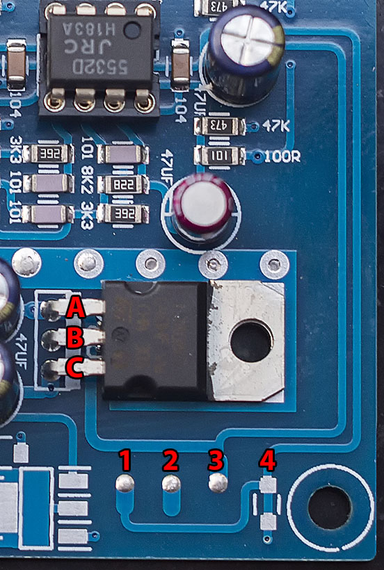
With the meter set to it's continuity setting, I'm getting a good circuit between A and 3 and between B and both 1 and 2.
Sorry for being a bit dense today, blame the bad head, but what else should I be measuring?
318 Digital Multimeter | Rapid Online
With the meter set to it's continuity setting, I'm getting a good circuit between A and 3 and between B and both 1 and 2.
Sorry for being a bit dense today, blame the bad head, but what else should I be measuring?
Attachments

Last edited:
Although a proper vacuum solder pump with a rework station is the ultimate, the second best and most cost efficient is this: Big Blue Solder Sucker.
It beats all of the smaller one's hands down (and I've used many), for it's vacuum capability, and IMNSHO any of the other options for desoldering through hole components is just a pain in the A$$.
Of course, removing surface mount components is another matter altogether, requiring solder wick, a liquid solder flux pen, maybe ChipQuick(is it the same thing?) and plenty of patience. I finally decided to break down and get an economical hot air rework station to make the job easier. (also easier to solder with SMD solder paste, although it also has it's challenges to not overdo how much to apply). I just got it and will be using it to do the mods on my 9038Q2M DAC board.
Last edited:
- Home
- Source & Line
- Digital Line Level
- ES9038Q2M Board