I'm delighted to report that all remaining M2x PCBoard sets have been requested.
However not all of them have been paid for, as yet.
Previous experience suggests that at least one or possibly two people will change their mind in the next few days, and forfeit their claims upon M2x boards.
So, starting now, PM requests for M2x boardsets will be recorded in a Waiting List. If two people back out of their purchase request, I'll contact the first two names on the Waiting List, offering the two forfeited boardsets.
If you are amazed (as I was!) that a diyAudio member would request a boardset, and then change his/her mind just a few days later, the reason given was usually, "I realized I already have a giant backlog of projects I haven't begun yet, and why spend another $50 that will only increase the backlog."
I am really amazed by the drive and eagerness of everyone here and the generosity and involvement of the 6L6, Mark, Jason, etc (and, of course, Mr. Pass!) Thank you! It's refreshing to witness all this.
One cannot stop to think here: "Hm, the ACA may be an interesting project... let me research and see if this could be my next proj...oh, ok, sold out...". I'm now all set for making the ACA and started to think into the future and about getting prepared for a possible next project. Deciding if it should be the F5t, the F6, the AlephJ, the M2x... Oh, wait, some boards available, that could be the right window, let me PM 6L6 with some quest.... oh, ok, sold out!")
This is great. I love it that there is no room for doubt here, you either jump right in or you are left behind. Really exciting stuff, and looking forward to all the people building the M2x.
Most likely this will be my next project, so I'll keep a close eye here. Good luck to all the early adopters and avid DIYers.
Best regards,
Rafa.
One cannot stop to think here: "Hm, the ACA may be an interesting project... let me research and see if this could be my next proj...oh, ok, sold out...". I'm now all set for making the ACA and started to think into the future and about getting prepared for a possible next project. Deciding if it should be the F5t, the F6, the AlephJ, the M2x... Oh, wait, some boards available, that could be the right window, let me PM 6L6 with some quest.... oh, ok, sold out!
This is great. I love it that there is no room for doubt here, you either jump right in or you are left behind. Really exciting stuff, and looking forward to all the people building the M2x.
Most likely this will be my next project, so I'll keep a close eye here. Good luck to all the early adopters and avid DIYers.
Best regards,
Rafa.
Last edited:
...personally, I'd put the M2x on the TOP of any to-do list, so you can listen to it's beautiful music as you work on all the rest.
It really is wonderful, this amp has a certain something that makes it particularly special.
I'm totally agree with you. This is the amp that make me stop building SS amp. Instead I built SET tube amp.
...personally, I'd put the M2x on the TOP of any to-do list, so you can listen to it's beautiful music as you work on all the rest.
It really is wonderful, this amp has a certain something that makes it particularly special.
Looking forward to it. Just ordered some Toshibas today
I haven't had a lot of chance to visit my favourite web site for a while, wow, Iv'e missed a lot of interesting stuff.
I think people may still like a hint on the core sound of each module, ie. out of the amplifier, I don't think it would spoil the fun, only add to the anticipation when you've built it; it may help in choosing to decide which one to build first, especially if your hobby time is tight.
Most hobbyists will have little experience with all the topologies, and will therefore be unfamiliar with their sonic signatures; only the hard core won't need the description, and they probably aren't reading this thread.
Lets face it, most people will want the ISHIKAWA, and no doubt they will ask 'what are the main (audiable) differences between it and the....'
Agreed. Properly done, buffers should be neutral. Mr Pass stated in post #266 that testing of the M2 was done with the preamp feeding the M2's transformer. He continued to say in the same post that the Toshibas know neutrality made it the choice...
This indicates to me that the main character of the M2 is what is after the buffer. This said, some of these buffers could be the equivalent of the original Toshiba buffer in the M2...well one sure ought to be anyway!
With the rarity of the linear parts, and the eventual depletion of Toshiba parts these front ends will be a welcome thing for future M2 builders.
As to how each of these new buffers will change the sound is unknown until tried, but it seems it would be a deviation from neutral, which is many times quite pleasant.
6L6 is familiar with my builds, as I followed his guides and made many inquiries to him. I only asked him as to his opinion on the "Tucson" as he knows how I reacted to the other builds. That said, until this project I dont think he had built a M2, so may not have had a chance to compare it (the original Toshiba front end) to Tucson for all I know!
I have M2 on hand, (Teabag version) and my next amp will be the V Fet project, so it will be a while before I can try the different front ends here.
I suspect that the main characteristic of original M2 isnt the buffer, but from the transformer on. This takes nothing away from the interesting experimentation with the alternative buffers here.
Russellc
Nobody will be burned at the stake, as the circuit needs more DC offset adjustment range than as originally published - I helped a local builder with his M2 project built on the excellent Tea-Bag PCB, and it also needed the pot and resistor changed to get the offset set to zero.
It's no big deal.
Thanks again. Rocking the Rockies!! I recorded this on my Android phone which doesn't even come close to the real thing. Just use your imagination. my new M2 build.
YouTube
I've received payment from everybody who requested M2x boardsets, thank you! This means there are no boards left over for anyone on the waiting list, regrettably.
I'll be traveling the next 7 days, and will ship out the M2x boardsets when I return, around June 14th. I'll send each buyer a PM showing the Customs Number and/or the USPS tracking number.
Thanks for buying,
Mark Johnson
I'll be traveling the next 7 days, and will ship out the M2x boardsets when I return, around June 14th. I'll send each buyer a PM showing the Customs Number and/or the USPS tracking number.
Thanks for buying,
Mark Johnson
Looking forward to it. Just ordered some Toshibas today
I have some coming also.
http://www.goldparts.de/shop/index.php?cPath=32_96_110&SESS=d4..
Those should make it sound richer...
More seriously, I have read the tread but think I missed the dimensions of the main PCB.
Cheers,
Max
EDIT: Never mind the question, looking a the pics I guestimate a length around 250mm (10 ") , that's close enough for now, boards are underway
Those should make it sound richer...
More seriously, I have read the tread but think I missed the dimensions of the main PCB.
Cheers,
Max
EDIT: Never mind the question, looking a the pics I guestimate a length around 250mm (10 ") , that's close enough for now, boards are underway
Last edited:
Somewhere, can't remember where, I promised some work on the AB100
pc board by way of update, and later decided that I would try melding it
with a modular output stage that would support an open design and
make it available through the store.
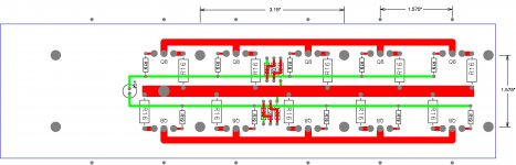
Toward that end I started fitting it to the UMS spec of DIYaudio, and here
it is currently, with up to 10 output devices and room for the 20 pin
socket holding a front end.
At this point I am just entertaining the notion of a layout that looks like
this with something like these dimensions.
These pinouts support complementary followers for TO-3P type packages
in both Bipolar and Mosfet. Digikey shows 95 such Bipolars.
Comments welcome.
pc board by way of update, and later decided that I would try melding it
with a modular output stage that would support an open design and
make it available through the store.
Toward that end I started fitting it to the UMS spec of DIYaudio, and here
it is currently, with up to 10 output devices and room for the 20 pin
socket holding a front end.
At this point I am just entertaining the notion of a layout that looks like
this with something like these dimensions.
These pinouts support complementary followers for TO-3P type packages
in both Bipolar and Mosfet. Digikey shows 95 such Bipolars.
Comments welcome.
Attachments
Somewhere, can't remember where...
It was here:
http://www.diyaudio.com/forums/pass-labs/227503-ab100-class-ab-power-amplifier-16.html#post5433439
Does the 20 pin socket you chose allow for a keyed positioning of the PCB? That would help less experienced builders avoid a mistake when attaching the front-end board.
Also, in the case of the AB100 amplifier, I believe many of the people interested in the project were expecting to hear your recommendations to replace the obsolete devices in the published schema.
Also, in the case of the AB100 amplifier, I believe many of the people interested in the project were expecting to hear your recommendations to replace the obsolete devices in the published schema.
Somewhere, can't remember where, I promised some work on the AB100
pc board by way of update, and later decided that I would try melding it
with a modular output stage that would support an open design and
make it available through the store.
Toward that end I started fitting it to the UMS spec of DIYaudio, and here
it is currently, with up to 10 output devices and room for the 20 pin
socket holding a front end.
At this point I am just entertaining the notion of a layout that looks like
this with something like these dimensions.
These pinouts support complementary followers for TO-3P type packages
in both Bipolar and Mosfet. Digikey shows 95 such Bipolars.
Comments welcome.
Very nice. Its M2X-ish as someone could make a unique input/driver board.
Would any benefit accrue from having hooks in the layout for soldering fat solid copper wires/rods to reduce the resistance of the high current traces?
I could see making the emitter resistors smaller if the output transistors were tightly matched thus making the resistance of the traces a critical path.
You could always re-layout a motherboard yourself, and include both wide traces and also buss-bar layout options. AWG-10 solid copper rods, or horseshoes, might be possibilities. Or machined aluminum bar stock.Would any benefit accrue from having hooks in the layout for soldering fat solid copper wires/rods to reduce the resistance of the high current traces?
The difficult part is circuit design, which First Watt has already supplied. All you need to do is lay out that circuit design on a PC board according to your own goals, with the power enhancements and optimizations that you have dreamed up.
Then plug in one of the front end PCBs using the new DIP-26 interface standard and Bob's your uncle.
You could always re-layout a motherboard yourself, and include both wide traces and also buss-bar layout options. AWG-10 solid copper rods, or horseshoes, might be possibilities. Or machined aluminum bar stock.
The difficult part is circuit design, which First Watt has already supplied. All you need to do is lay out that circuit design on a PC board according to your own goals, with the power enhancements and optimizations that you have dreamed up.
Then plug in one of the front end PCBs using the new DIP-26 interface standard and Bob's your uncle.
Is there a definitive write-up of the DIP 26 interface standard? I spent some time with the search feature to no avail.
- Home
- Amplifiers
- Pass Labs
- The diyAudio First Watt M2x