If I had good DC coming out of the wall, I'd probably use it. But I don't.If you guys need me, I'll be sitting at my kitchen table and pre-twisting solid-core filament wire with a cordless drill.
BTW, am I the only one who filters their AC for heaters? I haven't seen mention of it here. For example, I use inductive ballasts.
A matter of taste, the SPU is still for sale half a century later and I wish I could hear one in real. The old SPU I highly suspect should sound as good as all the new carts around 3k$.
if you sinned and bought a windfeldTi I am happy for you!
Last edited:
magnetic fields only exist due to current, voltage is only a potential and cannot cause any magnetic field.
Actually untrue,
Under what conditions is it not true? I have a hard time coming to terms with the idea of a voltage alone causing a magnetic field. Surely the voltage induces a current, which in turn induces the magnetic field?
To add a little confidence that many input stages can exhibit negligible hum from AC heater voltage leaking current through the cathode interface, the linked plot shows some bench setup hum levels for a simple 12AX7 gain stage.
I'll need to explain the setup a bit to avoid confusion about what the plots show - so bear with me") .
.
The 12AX7 circuit has a 10k grid leak, with unbypassed 1k5 cathode, and a 100k anode resistance to 240VDC B+. A 220nF coupling cap to a 100k load provides the output signal being measured for hum.
B+ is generated from a 12V battery through an isolated 12V to 430V dc/dc smps module (ebay cheapy) that is a bit modified, and nicely provides a floating DC B+ with no low frequency ripple content, with no AC mains hum loop concerns.
The heater voltage is a low distortion sine wave with pre-chosen frequencies of 50Hz, 100Hz, 300Hz and 1kHz. A USB mp3 player with the test tones feeds a 12V battery powered TDA7492 class D module amp. The worst heater voltage distortion was 0.07% with 1kHz, dropping to 0.01% at 50Hz. The heater voltage was 5.8Vrms at 50Hz and 6.1-6.2Vrms for the other frequencies, so the 50Hz signal is down -0.6dB. The heater voltage is floating - to avoid mains AC measurement hum loops.
The setup was confirmed to have a low noise floor with no low frequency signals poking out from the noise floor when un-powered or from the ~20dB higher 12AX7 circuit noise floor when powered with a battery DC heater voltage. The noise floor and signal spectrum was measured via a battery powered EMU0404 USB soundcard, and REW5 software on a PC (the only AC mains powered equipment).
The plots show the heater frequency (H1) hum signal level, normalised to 0dB for the 50Hz heater frequency hum level which was at or not too far under the noise floor. The 100Hz, 300Hz and 1kHz heater frequencies all had heater frequency hum levels above the noise floor.
The heater voltage was referenced to signal ground via a 200 ohm humdinger trimpot, which was tuned to minimise the heater frequency hum level - there was definitely a minima achieved, presumably balancing the stray capacitance leakage levels from the heater voltage wiring to the grid.
Of interest was that heater-cathode leakage was generating a significant 2nd harmonic (H2) of the heater frequency, which was not typically suppressed by humdinger nulling.
The tests were repeated with the heater at a positive DCV elevation (circa 30V from bypassed B+ divider).
The plots are a bit complicated to visualise as there is a curve for the heater frequency hum levels, and another curve for the second harmonic levels (ie. those plots start at 100Hz and extend to 2kHz), and repeated plots for when the heater was DCV elevated.
The 12AX7 had shown about 60Megohm Rhk from recent testing of heater-cathode resistance and capacitance with no DC elevation. I will need to check a few other 12AX7 in the same jig to see if that is at the lower end for Rhk.
Luckily we don't have mains AC frequency higher than 50/60Hz, as heater-cathode capacitance plays an ever increasing significance.
DCV elevation certainly lowers the fundamental heater frequency (H1) and the 2nd harmonic (H2) levels for 100Hz, due to increased Rhk. Improvement at 50Hz couldn't be confirmed due to the 12AX7 circuit noise floor.
Of course any typical input stage uses a bypassed cathode to suppress the hum leakage voltage between cathode and ground, and hence grid and cathode, which should push the output hum levels below the measurement noise floor (I'll try and confirm that in this setup soon).
https://dalmura.com.au/static/Hum%20plots%2012AX7.pdf
I'll need to explain the setup a bit to avoid confusion about what the plots show - so bear with me
.The 12AX7 circuit has a 10k grid leak, with unbypassed 1k5 cathode, and a 100k anode resistance to 240VDC B+. A 220nF coupling cap to a 100k load provides the output signal being measured for hum.
B+ is generated from a 12V battery through an isolated 12V to 430V dc/dc smps module (ebay cheapy) that is a bit modified, and nicely provides a floating DC B+ with no low frequency ripple content, with no AC mains hum loop concerns.
The heater voltage is a low distortion sine wave with pre-chosen frequencies of 50Hz, 100Hz, 300Hz and 1kHz. A USB mp3 player with the test tones feeds a 12V battery powered TDA7492 class D module amp. The worst heater voltage distortion was 0.07% with 1kHz, dropping to 0.01% at 50Hz. The heater voltage was 5.8Vrms at 50Hz and 6.1-6.2Vrms for the other frequencies, so the 50Hz signal is down -0.6dB. The heater voltage is floating - to avoid mains AC measurement hum loops.
The setup was confirmed to have a low noise floor with no low frequency signals poking out from the noise floor when un-powered or from the ~20dB higher 12AX7 circuit noise floor when powered with a battery DC heater voltage. The noise floor and signal spectrum was measured via a battery powered EMU0404 USB soundcard, and REW5 software on a PC (the only AC mains powered equipment).
The plots show the heater frequency (H1) hum signal level, normalised to 0dB for the 50Hz heater frequency hum level which was at or not too far under the noise floor. The 100Hz, 300Hz and 1kHz heater frequencies all had heater frequency hum levels above the noise floor.
The heater voltage was referenced to signal ground via a 200 ohm humdinger trimpot, which was tuned to minimise the heater frequency hum level - there was definitely a minima achieved, presumably balancing the stray capacitance leakage levels from the heater voltage wiring to the grid.
Of interest was that heater-cathode leakage was generating a significant 2nd harmonic (H2) of the heater frequency, which was not typically suppressed by humdinger nulling.
The tests were repeated with the heater at a positive DCV elevation (circa 30V from bypassed B+ divider).
The plots are a bit complicated to visualise as there is a curve for the heater frequency hum levels, and another curve for the second harmonic levels (ie. those plots start at 100Hz and extend to 2kHz), and repeated plots for when the heater was DCV elevated.
The 12AX7 had shown about 60Megohm Rhk from recent testing of heater-cathode resistance and capacitance with no DC elevation. I will need to check a few other 12AX7 in the same jig to see if that is at the lower end for Rhk.
Luckily we don't have mains AC frequency higher than 50/60Hz, as heater-cathode capacitance plays an ever increasing significance.
DCV elevation certainly lowers the fundamental heater frequency (H1) and the 2nd harmonic (H2) levels for 100Hz, due to increased Rhk. Improvement at 50Hz couldn't be confirmed due to the 12AX7 circuit noise floor.
Of course any typical input stage uses a bypassed cathode to suppress the hum leakage voltage between cathode and ground, and hence grid and cathode, which should push the output hum levels below the measurement noise floor (I'll try and confirm that in this setup soon).
https://dalmura.com.au/static/Hum%20plots%2012AX7.pdf
Last edited:
Under what conditions is it not true? I have a hard time coming to terms with the idea of a voltage alone causing a magnetic field. Surely the voltage induces a current, which in turn induces the magnetic field?
The original statement is nonsense as you well suspect, from here
Filaments DC or AC?
dB/dt = (c/S) Uac
The source of a time varying magnetic field B is a time varying voltage Uac.
For a DC voltage there is no induction
dB/dt = 0 ==> B = constant
Again, from post#83, for a current, the magnetic field H is given by
H = (4 π/cl) I
The source of a constant magnetic field H is a constant current Idc, and the source of a time varying magnetic field H is a time varying current Iac.
Roughly, the source of magnetic field B is voltage, and the sources of magnetic field H are currents.
Always is valid that
B = μ H
Last edited:
The heater voltage is a low distortion sine wave with pre-chosen frequencies of 50Hz, 100Hz, 300Hz and 1kHz. A USB mp3 player with the test tones feeds a 12V battery powered TDA7492 class D module amp. The worst heater voltage distortion was 0.07% with 1kHz, dropping to 0.01% at 50Hz. The heater voltage was 5.8Vrms at 50Hz and 6.1-6.2Vrms for the other frequencies, so the 50Hz signal is down -0.6dB. The heater voltage is floating - to avoid mains AC measurement hum loops.
Not me, but folks who use AC heaters often use 6V3 50Hz/60Hz, not 5V8.
What happens with higher order harmonics?
Just curious, DC heaters seems to me now easier than before...
That is Faraday's law of induction. I was under the impression it only works one way: the source of a time varying voltage Uac is a time varying magnetic field B, but a time varying electric field does not create a time varying magnetic field (except indirectly, by creating a current which in turn creates the magnetic field)? Change my mind.dB/dt = (c/S) Uac
The source of a time varying magnetic field B is a time varying voltage Uac.
Last edited:
Never mind, I'm talking out of my posterior as usual.That is Faraday's law of induction. I was under the impression it only works one way.
Under what conditions is it not true? I have a hard time coming to terms with the idea of a voltage alone causing a magnetic field. Surely the voltage induces a current, which in turn induces the magnetic field?
Thinking that all the fuss was over chicken-egg semantics is why I asked the question above.
That is Faraday's law of induction. I was under the impression it only works one way: the source of a time varying voltage Uac is a time varying magnetic field B, but a time varying electric field does not create a time varying magnetic field (except indirectly, by creating a current which creates the magnetic field)? Change my mind.
If you invoque causality, again, in classical mechanics, changes in momentum are caused by forces
d(mv)/dt = F
And again, following Bohr, the derivatives describes what is changing and the causes of the change are on the other side
dB/dt = (c/S) Uac
This equation says that the local cause of change in the magnetic field B is the time varying voltage Uac.
Of course, the equation also works the other way around, even more, most equations in physics also work with a reversal of time, thermodynamics put the limits here, and time travel to the past violates thermodynamics.
Strictly speaking, currents are related to the other magnetic field, H.
Using the constitutive relations (D=εE, B=μH), we have already discussed causality here
http://www.diyaudio.com/forums/tubes-valves/323196-filaments-dc-ac-10.html#post5448722
The conclusion was that electric and magnetic fields cause each other.
Let's left causality to the epistemology.
Never mind, I'm talking out of my posterior as usual.
Why? It is a very good question!
I think that a transformer is an enlightening example
An AC voltage on the primary produces a magnetic field B, which in turn induces a secondary AC voltage.
The magnetic field B reaches its maximum at no load, through the constitutive relation B=μH we can assign to B a current, which is in general very small and people call magnetizing current.
With load, secondary current creates a magnetic field Hs, but the corresponding primary current creates another magnetic field Hp, both Hs and Hp cancel each other.
Due to a finite primary winding resistance, with load the primary AC voltage is reduced a little bit and also does the magnetic field B.
Phenomenologically we can see the role of voltage and current, as the role of both magnetic fields B and H.
Last edited:
Practicalities can override perfection sometimes - the heater voltage signal source was mp3 files on a thumb size, rebranded, RCA TH1101 digital audio player - a device with only 30 volume setting steps - the device appears to have a HPF as all the mp3 files were prepared in the same manner.Not me, but folks who use AC heaters often use 6V3 50Hz/60Hz, not 5V8.
Higher order harmonics are way down - above the noise floor for 1kHz heater frequency, but imho of no importance for insight.What happens with higher order harmonics?
If you are starting with a commercial smps then I'd agree. If you have a more common power transformer then I'd say no, an AC heater is so much easier - the caveat being if you on a ship or plane with 400Hz AC power, or if you can't properly manage AC heater distribution and simple hum alleviation techniques.Just curious, DC heaters seems to me now easier than before...
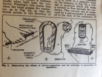
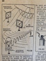
I found some illustrations for your discussion.
Are them from before or after Maxwell?
Practicalities can override perfection sometimes
It is not about perfection, but an approximation to reality, a reduced AC voltage yields a reduction of magnetic field B, even though it is between valve limits.
Higher order harmonics are way down - above the noise floor for 1kHz heater frequency, but imho of no importance for insight.
What about the yellow plot on 50Hz?
The magnetic field B goes as 1/f, so higher frequencies does not matters a lot, anyway it is weird the shape of the plot in black.
Maybe I did not understand the experiment?
If you are starting with a commercial smps then I'd agree. If you have a more common power transformer then I'd say no, an AC heater is so much easier - the caveat being if you on a ship or plane with 400Hz AC power, or if you can't properly manage AC heater distribution and simple hum alleviation techniques.
Hey, yesterday I was accused to having a $4000.- phono cartridge, today a ship and a plane...
The use of AC on heaters is still bloody complicated to my taste, I much prefer DC and avoid extra cabling on PCBs.
Last edited:
the caveat being if you on a ship or plane with 400Hz AC power, or if you can't properly manage AC heater distribution and simple hum alleviation techniques.
Lets travel by boat? Good one.
No one will make me use DC heaters, you can torture me, I will never let the enlarged blooming hysterical DC tube sound near me, I prefer class D.
On a positive ending, I do warm up the amps a few hours before listening. This cleans up the harmonics, clarify the sound and enhance details. Bias is same, temperature is same on components, nothing overheats, voltages are the same, THD is the same, except it sounds marvelously improved. That is what matters.
trobbins,
That was a great test. There are a couple more tests along that vein.
1. Imagine a cathode coupled phase splitter with a 12A_7, and a very high impedance current source in the coupled cathode circuit. There will likely be quite a bit of common mode hum in the plates due to the filament to cathode leakage and capacitance. The common mode hum will not likely be heard in the amp output. But it is an undesired signal that could potentially intermodulate with the music signals.
Part of the problem with an Ohmmeter to measure cathode to filament leakage is that it is different with the filament cold and the filament hot. If you want to measure it hot, you have to heat the filament, and disconnect the filament voltage, and then very quickly connect the Ohmmeter and take the reading.
2. There is the concertina phase splitter with 10k Ohm or larger cathode and plate load resistors. But this time the hum is not common mode, it is differential. And differential hum there will be heard in the amp output. That concertina stage will likely have more hum than your original test of the 12AX7.
But I have seen a 7199 triode section used as a concertina splitter with less than 100k Ohm cathode to filament leakage (even with the filament cold). This 7199 was used in a Dyna Stereo 70. The Dyna circuit is faulty with respect to the tube cathode to filament voltage ratings.
Last edited:
popolin, the test setup is aimed at measuring hum voltage level at the output of the first preamp stage in an amp, that is being induced by the heater voltage.
The first stage is typically the most sensitive stage to hum ingress, and I'd hazard a guess that the most ubiquitous first stage circuit is a simple cathode biased 12AX7, so given that the 'Filaments DC or AC' topic can be quite broad I've just limited my testing to that subset of stage/circuit topology.
The typical hum ingress means was discussed by Cooper back in 1944 (Valve Hum. C. E. Cooper, July 1944. Electronic Engineering, courtesy of Merlin):
The induced hum current paths due to the heater voltage can also be shown in the following simplified schematic:
So the test described in post #128 is not aimed at measuring hum induced by heater current flow per se.
For a 50Hz heater voltage frequency and DCV elevated heater, the 50Hz hum level at the output of the test stage was at or below about 6uVrms, and the 100Hz (H2) hum level was about 17uVrms. My HP3400A mV meter doesn't provide representative rms voltage levels below 100uVrms, so the comparison check of dB to Vrms was done at a somewhat higher level.
https://dalmura.com.au/static/Heater-cathode%20conduction%20plots.pdf
I used a different test jig to measure Rhk a few weeks ago, and that jig allowed Chk to be measured. There was no noticeable change in Rhk (or Chk) when the heater was powered compared to not powered - I did think that was an interesting outcome. That jig didn't allow me to DCV elevate the heater, and I may get a chance to check if I can't get around that limitation. That jig measured the Rhk and Chk between the total length of interface between heater and cathode. The heater wire is typically an 'out and back' wire in the cathode tube - so its likely in practise that the effective Rhk is 2x, and effective Chk is x0.5, as the heater AC voltage varies along the heater wire length.
But put in context, this detail is of little concern when the cathode bias resistor is sufficiently bypassed.
Ciao, Tim
The first stage is typically the most sensitive stage to hum ingress, and I'd hazard a guess that the most ubiquitous first stage circuit is a simple cathode biased 12AX7, so given that the 'Filaments DC or AC' topic can be quite broad I've just limited my testing to that subset of stage/circuit topology.
The typical hum ingress means was discussed by Cooper back in 1944 (Valve Hum. C. E. Cooper, July 1944. Electronic Engineering, courtesy of Merlin):
The induced hum current paths due to the heater voltage can also be shown in the following simplified schematic:
So the test described in post #128 is not aimed at measuring hum induced by heater current flow per se.
For a 50Hz heater voltage frequency and DCV elevated heater, the 50Hz hum level at the output of the test stage was at or below about 6uVrms, and the 100Hz (H2) hum level was about 17uVrms. My HP3400A mV meter doesn't provide representative rms voltage levels below 100uVrms, so the comparison check of dB to Vrms was done at a somewhat higher level.
My main incentive with this test was just to look at a typical input stage circuit and valve. The signal to hum ratio of stages after the first stage typically gets much better as the signal level is so much higher - but that said, if a subsequent stage couldn't suppress heater induced hum due to an inability to bypass a particular part of the circuit then yes that stage could become the dominant contributor of hum.There are a couple more tests along that vein.
I did some measurements of Rhk about 7 years ago with a test jig where the heater was powered:Part of the problem with an Ohmmeter to measure cathode to filament leakage is that it is different with the filament cold and the filament hot. If you want to measure it hot, you have to heat the filament, and disconnect the filament voltage, and then very quickly connect the Ohmmeter and take the reading.
https://dalmura.com.au/static/Heater-cathode%20conduction%20plots.pdf
I used a different test jig to measure Rhk a few weeks ago, and that jig allowed Chk to be measured. There was no noticeable change in Rhk (or Chk) when the heater was powered compared to not powered - I did think that was an interesting outcome. That jig didn't allow me to DCV elevate the heater, and I may get a chance to check if I can't get around that limitation. That jig measured the Rhk and Chk between the total length of interface between heater and cathode. The heater wire is typically an 'out and back' wire in the cathode tube - so its likely in practise that the effective Rhk is 2x, and effective Chk is x0.5, as the heater AC voltage varies along the heater wire length.
But put in context, this detail is of little concern when the cathode bias resistor is sufficiently bypassed.
Ciao, Tim
Last edited:
- Status
- This old topic is closed. If you want to reopen this topic, contact a moderator using the "Report Post" button.
- Home
- Amplifiers
- Tubes / Valves
- Filaments DC or AC?