")
... The 3-pin connector is electrically connected to the PC so I suggest to use a transformer as well, to isolate it. ...
I'm not familiar with S/PDIF transformers, is the Murata DA101MC ok:
DA101MC Murata Power Solutions | Mouser
or better recommendations?
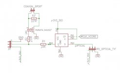
Digital output adapter
I think R3 is traditionally placed on the primary side of the pulse transformer... effectively in parallel with the source and series impedances.
Cheers
Do you mean, something like that?
I think R3 is traditionally placed on the primary side of the pulse transformer... effectively in parallel with the source and series impedances.
Cheers
@cwtim01
I have used a Murata DA102C.
@lemon
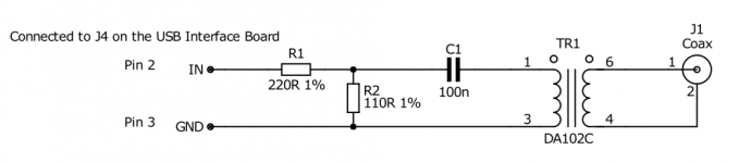
The flip-flop is already on the USB Interface Board. So all you need to make an isolated SPDIF output is shown on the attached schematic. The capacitor may not be needed, but I prefer to run the transformers with no DC current.
I have used a Murata DA102C.
@lemon
The flip-flop is already on the USB Interface Board. So all you need to make an isolated SPDIF output is shown on the attached schematic. The capacitor may not be needed, but I prefer to run the transformers with no DC current.
Attachments
I've been using mine for audio measurements on my latest amplifier design and am very pleased with the performance. (I've yet to install the updates, but will.)
The spdif out option is a welcome future enhancement I will add if and when I need it.
The RTX is so much better than what it replaced even my jaded engineer friends remark on just how clean it is.. (wrt instrument residuals)
The spdif out option is a welcome future enhancement I will add if and when I need it.
The RTX is so much better than what it replaced even my jaded engineer friends remark on just how clean it is.. (wrt instrument residuals)
I made a quick bread board version for the SPDIF output and as suspected the oscillation of the overshot is no longer there with SPDIF (or at least much weaker).
Here a recording to compare: Upper pair = (Source, via-SPDIF-recording), lower pair = (Source, via-USB-recording)

Here the same more zoomed in:

I do not see in the data sheet of the ADC the filter coefficients of the input LP/decimation-fiter. It would be useful to know them, as then one could estimate from the shape of the overshot where the flank of the square wave is located (time wise, in the interval of one sample).
Here a recording to compare: Upper pair = (Source, via-SPDIF-recording), lower pair = (Source, via-USB-recording)
Here the same more zoomed in:
I do not see in the data sheet of the ADC the filter coefficients of the input LP/decimation-fiter. It would be useful to know them, as then one could estimate from the shape of the overshot where the flank of the square wave is located (time wise, in the interval of one sample).
I used an commercial XLR-BNC adapter (pin 1,3 shorted) on the input of the RTX6001 now the first time since I did the resistor-cap-mod that came with the shields. There is now, with the adapter, a lot more 50Hz hum and harmonics than I remember for before the mod.
Here a picture of a measurement of a loopback with no signal playing (input=output setting = 0dBv). With the adapter alone (floating) it looks alike.

I started playing around a bit an noticed that also with an 1m XLR cable connected to the input only (floating) there are funny artefacts.

However when making the single ended connection as recommended, terminating the XLR-BNC adapter with 50Ohm, leaving the input unconnected, or connecting the XLR cable also to the output, the measurements are fine as ever.
Here a picture of a measurement of a loopback with no signal playing (input=output setting = 0dBv). With the adapter alone (floating) it looks alike.
I started playing around a bit an noticed that also with an 1m XLR cable connected to the input only (floating) there are funny artefacts.
However when making the single ended connection as recommended, terminating the XLR-BNC adapter with 50Ohm, leaving the input unconnected, or connecting the XLR cable also to the output, the measurements are fine as ever.
I used an commercial XLR-BNC adapter (pin 1,3 shorted) ---
However when making the single ended connection as recommended, terminating the XLR-BNC adapter with 50Ohm, leaving the input unconnected, or connecting the XLR cable also to the output, the measurements are fine as ever.
Can you explain "terminating the XLR BNC adapter( ?) with a diagram to understand this ? I take it that the source has issues terminating on the RTX input ?
I would have preferred - RTX having appropriately designed single ended alternate input like Audio Precision with lower S/N. Easier to deal with for users like me. I had already lost two 1K5 resistors trying to solder the SMD ones for mod sent by RTX -outside the RTX chassis ! I do not feel confident doing it inside the RTX so far.
kannan
Just to clarify, the four cases
With terminating with 50Ohm, I mean I put an 50Ohm terminating BNC-plug on the XLR-BNC adapter. So no signal measurement, but just the noise floor.
are four independent cases when RTX just gives fine results.the single ended connection as recommended, terminating the XLR-BNC adapter with 50Ohm, leaving the input unconnected, or connecting the XLR cable also to the output
With terminating with 50Ohm, I mean I put an 50Ohm terminating BNC-plug on the XLR-BNC adapter. So no signal measurement, but just the noise floor.
Last edited:
thanks - does it mean, the solution given works or creates new issues that were not present earlier?
I am not entirely sure.
I can not remember it that bad, but I find no own measurements with the entirely identical setup.
I made just made a measurement with the settings (0dBV out, -20dBV in) as Jens here:DIY Audio Analyzer with AK5397/AK5394A and AK4490

It looks alike but perhaps slightly worse.
If I compare with my own measurements here
DIY Audio Analyzer with AK5397/AK5394A and AK4490
it looks definitely worse, but there I used a cable with pin 1,3 shorted (I no longer have) not the adapter.
Perhaps Jens can reproduce his measurement with the modified RTX.
Toslink offers isolation - whats not to like?
It is not that easy to find transmitters/receivers which support 192kHz-Audio.
I have read (but not verified myself) that jitter is worse than SPDIF.
I would prefer an I2S output above both - e.g. AD claims for it's AD1955 Eval board that it performs better jitter and noise wise with I2S than with Toslink or SPDIF.
It is not that easy to find transmitters/receivers which support 192kHz-Audio.
Very easy:
Fiber Optics - Receivers | Optoelectronics | DigiKey
Fiber Optics - Transmitters - Drive Circuitry Integrated | Optoelectronics | DigiKey
It is not that easy to find transmitters/receivers which support 192kHz-Audio.
I have read (but not verified myself) that jitter is worse than SPDIF.
I would prefer an I2S output above both - e.g. AD claims for it's AD1955 Eval board that it performs better jitter and noise wise with I2S than with Toslink or SPDIF.
With modern receiver ICs this is a non-issue.
16Mbps is tight, you should look for 25Mbps for a reliable connection.
With modern receiver ICs this is a non-issue.
Not everything I want to measure is "modern" ;-)
- Home
- Design & Build
- Equipment & Tools
- DIY Audio Analyzer with AK5397/AK5394A and AK4490