IIRC, the schematic Madds showed had a 10uf electrolytic to ground on the DAC1B output and sort of a IV connection on the DAC1A output. Given Ro for the DAC channels, 10uf probably is not enough capacitance to hold the one DAC output at a fixed voltage at low frequencies. If the cap were bigger, then it would tend to charge up to a fixed DC voltage which happens to be 1/2 AVCC (the average DAC output voltage in voltage-mode). In that case, the circuit would look like an IV on DAC1A only, with the IV offset to 1/2 AVCC. At least that's the way it looks to me.
I have to agree that there is more in a good implementation than THD numbers show. It appears there may be more than one way to get very good sound out of this DAC. What seems to be lacking is any way to compare outcomes of the different but successful ways to get very satisfying sound quality. I have already said that what I am using here as something to compare my modified Chinese DAC to is a Benchmark DAC-3. Don't know if anybody else has said what DAC they are using to compare with (since I think we already agree, THD numbers don't show everything).
DAM 1021,diyhink AD1865+ Burson V5,AD1865 full tube dac with 6N23P,to compare.
Democles, have you done measurements?
I only put some sine waves throu it, they look good.
I cant mesure THD etc.
I cant mesure THD etc.
Do you have a sound card with a line level input?
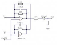
IIRC, the schematic Madds showed had a 10uf electrolytic to ground on the DAC1B output and sort of a IV connection on the DAC1A output. Given Ro for the DAC channels, 10uf probably is not enough capacitance to hold the one DAC output at a fixed voltage at low frequencies. If the cap were bigger, then it would tend to charge up to a fixed DC voltage which happens to be 1/2 AVCC (the average DAC output voltage in voltage-mode). In that case, the circuit would look like an IV on DAC1A only, with the IV offset to 1/2 AVCC. At least that's the way it looks to me.
That is correct. I set the LPF at 2hz with a 100uF. 10uF was a typo in my last post and the diagram.
I know this circuit works and puts one leg in current mode just like the Sabre recommendation. The only difference is I am deriving AVCC/2 from the other leg via the LPF
Anyhow - here is napkin drawing that originally posted
http://www.diyaudio.com/forums/digital-line-level/314935-es9038q2m-board-47.html#post5387750
Please poke holes in this approach. As far as I know - this is the easiest way to get the DAC board in unbalanced current mode
Cheers
Madds,
The problem with Sabre is that they are skimpy with their information. If the chip contains a charge pump to double the voltage, 3.3V would be right in the middle. Basically, it was a wild shot when I mentioned this, it might be ok to follow the Sabre paper on this point, but it deals with a different DAC. Measuring Vout from the DAC is the best way to find out where to bias the opamp. Since all my measurements were done in balanced mode, I didn't bother to measure it when my board was still operation.
Can you please post the schematic along with your questions again, I'll be happy to respond.
Please
Hope this helps. The cap is actually 100uf unlike the 10uf shown
http://www.diyaudio.com/forums/digital-line-level/314935-es9038q2m-board-47.html#post5387750
Victor's high-performance solution for SE output isn't much more difficult: Chinese ES9018K2M I2S DAC
Don't have the DS for the 9038q2m to know how much you need to scale the resistors vs the 9018k2m, but it all depends on what output you want as well. Compensation may need a little fiddling, too, if the overall gain is lower.
Don't have the DS for the 9038q2m to know how much you need to scale the resistors vs the 9018k2m, but it all depends on what output you want as well. Compensation may need a little fiddling, too, if the overall gain is lower.
Victor's high-performance solution for SE output isn't much more difficult: Chinese ES9018K2M I2S DAC
Don't have the DS for the 9038q2m to know how much you need to scale the resistors vs the 9018k2m, but it all depends on what output you want as well. Compensation may need a little fiddling, too, if the overall gain is lower.
DPH
Not saying it is difficult. Just saying that this is the quick way to get to current mode without doing too much and with a single opmap. Literally short 8 resistors and add a 2 caps
Don't know if Vic solution measures better than Sabre's recommendation but here it is
Cheers
I think Daniel is referring specifically to the circuit shown below. Victor also said he used 3 x 1800uf caps in parallel with a tantalum already there for AVCC conditioning. This was for a Chinese ES9018 DAC board. Resulting harmonic and intermodulation distortion were measured as virtually completely down in the noise at -120dB or so. Only exception was a little 3rd harmonic seen at around -115dB when at FS output. Who knows, maybe a little bit of intersample overs there?
Hey, speaking of intersample overs, is anyone doing anything about that besides me? Since I am hardware upsampling before the ESS DAC chip, I am using the SRC chip to attenuate output level by 3.5dB in order to solve the intersample over issue at the same time as eliminating audibility of the DAC reconstruction filter. Definitely sounds better that way, trust me.
Might be worth mentioning at this time that abraxalito found this neat SRC pcb here: SRC4392 asynchronous rise frequency decode board (with USB/ Coaxial / fiber /I2S)-in FM Transmitters from Automobiles & Motorcycles on Aliexpress.com | Alibaba Group
Although the board as-is does not offer attenuation, the SRC4392 chip is easily capable of it. I can provide Arduino code for anyone interested to set it up as I do for the DAC. Also, might mention that the SRC4392 is rated for -140dB THD. It won't hurt the bits at all, relative to what the DAC itself is capable of.
Also found what I hope will be a cheaper way to get USB than other alternatives which is this board: CM6631A Digital USB to IIS SPDIF Module 24bit 192khz I2S Converter Board | eBay
Attachments
Last edited:
I run everything from a computer (not on this DAC, yet, still working through other projects, and debating 4490 vs this), so inter-overs are something I manage with volume there (-6 dB hard cut in digital) and never really worry about, as I'm more worried about too much attenuation than the opposite.
And, yes, my recommendation of Victor's circuit comes with the very good result he measured.
And, yes, my recommendation of Victor's circuit comes with the very good result he measured.
All nice things to try.
But dont you want the dac to sound first great /decent and after that do something with the I/V ore amplification.
This dac is short on base and soundstage.
So put in a lot of uF on the AVCC and tune it from there to a F1 race car.
At least you have something to mod with.
The plain PCB has not mutch.
@democles, Agreed that the DAC board needs good AVCC, good overall power for everything, and a good IV stage. Those are good places to start.
It also helps to replace the clock oscillator module with an ultra-low jitter type. The jitter needs to be low down around 10Hz, which most low jitter oscillators can't do. They are good at maybe 12kHz, not much lower.
In addition to the above, upsampling the digital input to as high as possible (211kHz is ideal, but higher than your source material sample rate is good enough), while using the slow-transition, miminum-phase reconstruction filter helps a lot too.
In addition, a good headphone amp or other reproduction system is needed, as the DAC opamp output will distort somewhat if it is used to drive headphones directly. And, making a good headphone amp brings its own set of issues to work out for best results.
As hopefully can be seen, there are several things to address to get truly excellent SQ from an ES9038Q2M DAC chip. just doing an output stage and some AVCC improvement is not enough to really get the most out of the DAC in terms of SQ.
Unfortunately, what it means to me is a really first-class SQ, low-cost DAC is going to end up being more expensive than I would have preferred. Cost could be reduced quite a bit by making a new board with everything needed on it, at least as compared to all this getting-a-few-boards, integrating-them-together, and modifying-them-for-better-performance phase of development.
Unfortunately, what it means to me is a really first-class SQ, low-cost DAC is going to end up being more expensive than I would have preferred. Cost could be reduced quite a bit by making a new board with everything needed on it, at least as compared to all this getting-a-few-boards, integrating-them-together, and modifying-them-for-better-performance phase of development.
I am Dutch, so expensivi is a no go
Yep, it wil get more expensive, but with more uF on the AVCC it wil be your
choice to go further or stop.
So dit 40 euro on the dac 20 euro on the 15v fore the opamp, 30 euro on the 3 Salas shunt,s,10 euro fore the litle things and 20 euro on the rest.
I am Dutch, so expensivi is a no go
Yep, it wil get more expensive, but with more uF on the AVCC it wil be your
choice to go further or stop.
So dit 40 euro on the dac 20 euro on the 15v fore the opamp, 30 euro on the 3 Salas shunt,s,10 euro fore the litle things and 20 euro on the rest.
Last edited:
It also helps to replace the clock oscillator module with an ultra-low jitter type. The jitter needs to be low down around 10Hz, which most low jitter oscillators can't do. They are good at maybe 12kHz, not much lower.
We are using newest NDK clocks NZ2520SDA that has good phase noise down to 10hz (sorry I cannot find the graph)
Right now all ess sabres DAC use ASRC , because most sources are jittery. The Sabre team did a great job no doubt...but the new sabre CAN run in master mode.
You want good SQ ? Get rid of ASRC and use master. (i2s).
Hope this helps. The cap is actually 100uf unlike the 10uf shown
http://www.diyaudio.com/forums/digital-line-level/314935-es9038q2m-board-47.html#post5387750
This will work for the chip specified for the development board, better measure output level offset of the 9038 to be sure. That's what I would do.
As a beside, it is not a good idea to only use one channel of the DAC for output, unless your reference voltage is rock solid. On the standard board it isn't. There is a reason why these chips have balanced output: so that reference voltage fluctuations are translated into common mode swings. If you want single output, better use victors schematic.
You want good SQ ? Get rid of ASRC and use master. (i2s).
I would agree it is one thing that can help SQ (along with all the other things) in applications where it is feasible. However, a general purpose DAC may have to play music from any source and do so using common interface standards, such as AES/EBU, USB, Coaxial SPDIF, and TOSLINK. In most general use cases, there is going to have to be ASRC somehow or other.
Having said the above, ASRC in ES9028 and 38 are quite a bit better than ES9018. Also, for people choosing to upsample with something like SRC4392, it can be clocked via I2S using ES9038 in master mode, if desired.
- Home
- Source & Line
- Digital Line Level
- ES9038Q2M Board