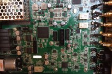
RustySpoons, Just looked at the kit and also the link they have there that shows the finished board. It looks like there are only enough opamps there for modest conditioning of AVCC (maybe only using a voltage regulator for that), and maybe one left and one right channel IV conversion. One of the reasons for using a full ES9038 instead of the Q2M version is that the big chip has 8 output channels that can be combined into 2 groups of 4 channels. Using them all that way gives the best results and lowest noise. Also, the big oscillator can doesn't necessarily mean you get a truly low phase noise oscillator. The one I used is much smaller, and the ones Benchmark uses in DAC-3 are are a bit smaller than what I used.
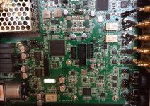
For reference and to make a sort of overboard comparison I will see if I can post a few pictures of a DAC-3 board below. (Posted more than one because they are not all equally in focus across the board.)
Getting back closer to reality for a kit, it would be very hard to tell what you would be getting without a parts list and a schematic, or alternatively perhaps some measurements and listening test reviews. It seems like kind of a shot in the dark.
Then again, assembling it yourself you might be able to use any extra unused output channels to experiment with other IV circuits while leaving the default circuits included with the kit fully intact.
If you decide to go ahead with it, please keep us informed of how it is coming along and how you like the sound quality. Also, if you are able to sketch out a schematic, it would probably of great interest to folks here in the forum.
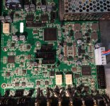
Attachments
Last edited:
RustySpoons, Just looked at the kit and also the link they have there that shows the finished board. It looks like there are only enough opamps there for modest conditioning of AVCC (maybe only using a voltage regulator for that), and maybe one left and one right channel IV conversion. One of the reasons for using a full ES9038 instead of the Q2M version is that the big chip has 8 output channels that can be combined into 2 groups of 4 channels. Using them all that way gives the best results and lowest noise. Also, the big oscillator can doesn't necessarily mean you get a truly low phase noise oscillator. The one I used is much smaller, and the ones Benchmark uses in DAC-3 are are a bit smaller than what I used.
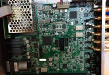
For reference and to make a sort of overboard comparison I will see if I can post a few pictures of a DAC-3 board below. (Posted more than one because they are not all equally in focus across the board.)
Getting back closer to reality for a kit, it would be very hard to tell what you would be getting without a parts list and a schematic, or alternatively perhaps some measurements and listening test reviews. It seems like kind of a shot in the dark.
Then again, assembling it yourself you might be able to use any extra unused output channels to experiment with other IV circuits while leaving the default circuits included with the kit fully intact.
If you decide to go ahead with it, please keep us informed of how it is coming along and how you like the sound quality. Also, if you are able to sketch out a schematic, it would probably of great interest to folks here in the forum.
Hi Markw4,
Thank you for the reply and information.
I probably won't go for that specific kit, it looked interesting so thought I would share it on here. It also requires a board to convert I2S to USB or whatever format one wishes to use as it does not come with one.
I thought it looked quite interesting so thought I would share, I will order a more basic board/kit and build around that as this has things I don't need.
Hi Mark, could you plse share with us the opamps used in the Benchmark?
I can see there are multiple LME49860's. It appears to have +-18v rails.
Last edited:
Tnx Daniel. 5532 is still phenomenally good. TI uses them in their recommended PCM1794 implementation! Just ordered this board:
ES9038Q2M ES9038 I2S Ingang versterker Decoders Mill Board DAC Decodering Board in ES9038Q2M ES9038 I2S Ingang versterker Decoders Mill Board DAC Decodering Board van Versterker op AliExpress.com | Alibaba Groep
Because I improved another model until it broke.
ES9038Q2M ES9038 I2S Ingang versterker Decoders Mill Board DAC Decodering Board in ES9038Q2M ES9038 I2S Ingang versterker Decoders Mill Board DAC Decodering Board van Versterker op AliExpress.com | Alibaba Groep
Because I improved another model until it broke.
Tnx Daniel. 5532 is still phenomenally good. TI uses them in their recommended PCM1794 implementation! Just ordered this board:
ES9038Q2M ES9038 I2S Ingang versterker Decoders Mill Board DAC Decodering Board in ES9038Q2M ES9038 I2S Ingang versterker Decoders Mill Board DAC Decodering Board van Versterker op AliExpress.com | Alibaba Groep
Because I improved another model until it broke.
Why can't I see a like button on this forum
")
That's one I'm looking at, a lot of the others have adjustments for filters which I cannot be bothered with. This looks nice and simple to easily modify and build around.
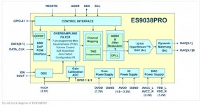
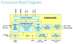
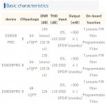
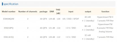
Sometimes people ask what differences there are between an ES9038Q2m and an ES9038PRO. I found some info out on the net an shown in the images below.
Attachments
I can see there are multiple LME49860's. It appears to have +-18v rails.
And just to be thorough, 49720 and 49860 are the same chip with different voltage ratings.
I know you know this, Mark.
Furthermore, I found that the ES9038 board has higher than necessary distortion because of insufficient decoupling of the analog supply rail to the DAC. Mounting a largish cap underneath the board, using the pins that protrude from the board of the 47uF caps mounted above, brings significant improvements. You can improve low end distortion reduction by about 8dB, just by mounting 2200uF caps at this location.
I just tried to add a 2200uF capacitor on one channel (the one with current mode output). I got an improvement of 3.8dB at 1kHz 0dBFS. The THD went from -103.2dB to -107dB.
On my board, V1.04, there are 100uF capacitors on the AVCC_L and AVCC_R, not 47uF.
Jens, I got a further improvement by almost 6dB by putting a small resistance between dac and iv converter, very surprising. -113dB or better is what I got before the board failed. Not at home now, will post measurement tomorrow. I used 2.7 Ohm, but a bit lower might be better but had to stop experiment.
This does not work with es9018.
This does not work with es9018.
May I ask what digital output level you guys are using to measure distortion? Just want to be sure no intersample overs are affecting measurements.
@vacuphile, could it be that the 2.7 ohm series resistance helps limit modulation of AVCC if regulating it with an RC filter, rather than if using an opamp-based regulator?
Also, I would be happy to try the low-series-resistance experiment here, but I need to get my notch filter working first. Otherwise, I would potentially be getting down around the residual distortion of my ADC.
Mark, that is my assumption also, but in a way it does not make sense. Ro of the dac I guestimate to be around 600 Ohm, a couple of Ohms in series with that will not affect current draw by a significant percentage.
I need to make a notch filter too for the same reasons. I am too close to the floor of my test equipment to be confident about what I measure, have the same problem with composite amps I am looking into.
I need to make a notch filter too for the same reasons. I am too close to the floor of my test equipment to be confident about what I measure, have the same problem with composite amps I am looking into.
I am unable to share the documents because of the NDA..
Basically here are some registers in the ess sabre that can compensate the analog stage and thus you can get better THD (7-10db) on H2 and H3
I am measuring only THD at this point since our machine apx515 has a residual floor of -102Thd+n. We are at -102.9 (so at the floor)
So we are looking at the harmonics now (since noise is more benign anyway). Last test we had H2 -123.4 , h3 -124.85 (only 3h was compensated )
Yes A weighted
- Home
- Source & Line
- Digital Line Level
- ES9038Q2M Board