For those who might be interested: Here is the definitive explanation of what PMA is concerned with, THERMAL FEEDBACK.
Unfortunately, the paper: Solomon 'The Monolithic OP AMP: A Tutorial Study' is too long to be put up here. It is in the Nov 1974, IEEE Journal of Solid State Circuits, and other sources such as National Semiconductor. Look it up.
That's exactly NOT what Pavel wrote, and he clarified that it's mostly he can't get the heat out of the chip due to packaging. Similarly, Scott reminded me that symmetric layout obviates that concern.
Now, Solomon's paper is a pretty good read if I'm remembering correctly.
For those who might be interested: Here is the definitive explanation of what PMA is concerned with, THERMAL FEEDBACK.
Unfortunately, the paper: Solomon 'The Monolithic OP AMP: A Tutorial Study' is too long to be put up here. It is in the Nov 1974, IEEE Journal of Solid State Circuits, and other sources such as National Semiconductor. Look it up.
Problem identified problem solved decades ago, you fail to note the problem is not inherent and easily designed around.
Even 48 years ago, http://www.analog.com/media/en/analog-dialogue/volume-4/number-2/articles/volume4-number2.pdf
Last edited:
![323595.fig.008[1].jpg](https://www.diyaudio.com/community/data/attachments/605/605105-d907a58f653dfcd023f843f640d7f97e.jpg "323595.fig.008[1].jpg")
http://hifisonix.com - James-E-Solomon-Opamp-Tutorial.pdfFor those who might be interested: Here is the definitive explanation of what PMA is concerned with, THERMAL FEEDBACK.
Unfortunately, the paper: Solomon 'The Monolithic OP AMP: A Tutorial Study' is too long to be put up here. It is in the Nov 1974, IEEE Journal of Solid State Circuits, and other sources such as National Semiconductor. Look it up.
Bonsai has also collected a bunch of articles -
Audio Design Library
Useful Audio Links
Dan.
A poor question.Here's a nice topology --- where would the cm signal be derived from on this circuit? VCMFB.
I will answer a much narrower, much better question: "From where would YOU derive the common mode signal, in this circuit?"
My own answer is: I would derive it from a little blob of a few CMOS transistors, the inputs to this little blob being Vout+, Vout-, and DesiredVcmReference. I would of course take advantage of the fact that nearby transistors on CMOS chips are well matched and, if necessary care is taken, extremely well matched.
From where would YOU derive the common mode signal?
A poor question.
I would start with "nice topology" why? Anything further is pushing it.
You have to very carefully read the spec sheet and ignore the marketing claims.
Who the hell comes up with marketing claims for datasheets? super annoying... but yes, I know what you mean. Usually if they even rate the distortion or output at the voltage max, it's obviously unusable. My point is just that chips can work fine, you just can't run them all that close to supposed maximums.
Hi everybody! Have you read or at least looked through the OP Amp Tutorial from Solomon? The thermal feedback problem is something that IC power amps could have plenty of, because the output devices are on the chip with the input devices, AND they have to work so hard, in order to actually drive the speaker that they often overheat the total chip, as well as modulating the input devices, creating another distortion mechanism. Of course, the IC layout can 'minimize' this, but to remove it completely is probably not possible with a power amp.
IF you read Solomon's Tutorial, you will learn what we have known for the last 40+ years about linear amp design with regards to slew-rate, as well.
IF you read Solomon's Tutorial, you will learn what we have known for the last 40+ years about linear amp design with regards to slew-rate, as well.
A great question.")
I will answer a much narrower, much better question: "From where would YOU derive the common mode signal, in this circuit?"
My own answer is: I would derive it from a little blob of a few CMOS transistors, the inputs to this little blob being Vout+, Vout-, and DesiredVcmReference. I would of course take advantage of the fact that nearby transistors on CMOS chips are well matched and, if necessary care is taken, extremely well matched.
From where would YOU derive the common mode signal?
Have you tried a DDA in any circuits? Differential Difference Amplifier?
http://workshop.ee.technion.ac.il/upload/files/Shraga Kraus.pdf
http://shodhganga.inflibnet.ac.in/bitstream/10603/5652/8/08_chapter 3.pdf

THx-RNMarsh
Last edited:
Have you tried a DDA in any circuits? Differential Difference Amplifier?
http://workshop.ee.technion.ac.il/upload/files/Shraga Kraus.pdf
http://shodhganga.inflibnet.ac.in/bitstream/10603/5652/8/08_chapter 3.pdf
View attachment 670023
http://shodhganga.inflibnet.ac.in/bitstream/10603/5652/8/08_chapter 3.pdf
file:///C:/Users/Richard/AppData/Local/Packages/Microsoft.MicrosoftEdge_8wekyb3d8bbwe/TempState/Downloads/1999.PDF
last one is a Current-mode feedback version of DDA.
THx-RNMarsh
Last edited:
Hi everybody! Have you read or at least looked through the OP Amp Tutorial from Solomon? The thermal feedback problem is something that IC power amps could have plenty of, because the output devices are on the chip with the input devices, AND they have to work so hard, in order to actually drive the speaker that they often overheat the total chip, as well as modulating the input devices, creating another distortion mechanism. Of course, the IC layout can 'minimize' this, but to remove it completely is probably not possible with a power amp.
IF you read Solomon's Tutorial, you will learn what we have known for the last 40+ years about linear amp design with regards to slew-rate, as well.
It seems, we have Dunning & Kruger doing overtime.
No, audio design is not a mythical thing that EEs cannot grasp by definition and that's only accessible to priests who are not tainted by systematic education in the area.
What cheek to present a 40 year old introduction to op amps as a freshly excavated scroll, unbeknownst to all but a few true gurus! As if the complete National Semiconductor book series hadn't been on everyone's table back then.
But that is consistent with someone who tries to sell the same circuit since 40 years, even when the parts for it have become unobtainium since their makers decided that they filled a badly needed void.
And no, integrated "power" amplifiers have no bad offset problems, let alone distortion for thermal reasons. But it takes understanding the essentials of feedback.
Yesterday, I found a nice picture of Bob Widlar and I cannot resist to pass it on, since it sums up everything in a very compact form.
Attachments

Yes. The problem is double.Have you tried a DDA in any circuits? Differential Difference Amplifier?
Nulling the signal between an input and an output of an amplifier, as an example, request you have to attenuate the output in a ratio that have to be exactly the gain of the amplifier: not so easy, if you want to dig in <0.1% of distortion.
The second problem is, even if there is no change in the quality of the signal (no harmonic distortion), at HF, the slightest phase difference will produce an unwanted error signal. And even the capacitance of the probe (+ measuring circuit input capacitance) can turn the phase.
That could certainly be the case, been through this with ADSL drivers the original AD815 had the right if not cost effective package.
Indeed they had ;-)
Attachments
@ JC:
John did you miss Scotts post:
"Problem identified problem solved decades ago, you fail to note the problem is not inherent and easily designed around.
Even 48 years ago, http://www.analog.com/media/en/analo...e4-number2.pdf"
Jan
Hi everybody! Have you read or at least looked through the OP Amp Tutorial from Solomon? The thermal feedback problem is something that IC power amps could have plenty of, because the output devices are on the chip with the input devices, AND they have to work so hard, in order to actually drive the speaker that they often overheat the total chip, as well as modulating the input devices, creating another distortion mechanism. Of course, the IC layout can 'minimize' this, but to remove it completely is probably not possible with a power amp.
IF you read Solomon's Tutorial, you will learn what we have known for the last 40+ years about linear amp design with regards to slew-rate, as well.
John did you miss Scotts post:
"Problem identified problem solved decades ago, you fail to note the problem is not inherent and easily designed around.
Even 48 years ago, http://www.analog.com/media/en/analo...e4-number2.pdf"
Jan
Last edited:
Yes. The problem is double.
Nulling the signal between an input and an output of an amplifier, as an example, request you have to attenuate the output in a ratio that have to be exactly the gain of the amplifier: not so easy, if you want to dig in <0.1% of distortion.
The second problem is, even if there is no change in the quality of the signal (no harmonic distortion), at HF, the slightest phase difference will produce an unwanted error signal. And even the capacitance of the probe (+ measuring circuit input capacitance) can turn the phase.
It sure seems popular for bal/unbal.
THx-Richard
Last edited:
Indeed they had ;-)
I have noticed that the latest Intersil smart power stages used in top PC motherboards are using a new QFN package with exposed thermal pads on both sides. Using the PCB as a heatsink is nice for cost saving but it's good to be able to mount the part directly to something. The newer ADSL drivers are thermally designed with the application's crest factor in mind I guess.
Yes. The problem is double.
Nulling the signal between an input and an output of an amplifier, as an example, request you have to attenuate the output in a ratio that have to be exactly the gain of the amplifier: not so easy, if you want to dig in <0.1% of distortion.
Professor, do you realize that the feedback 'automagically' adjusts the closed loop gain to minimize the effective input signal on the input pins to be just enough to support Vout through the open loop gain?
Jan
I have noticed that the latest Intersil smart power stages used in top PC motherboards are using a new QFN package with exposed thermal pads on both sides. Using the PCB as a heatsink is nice for cost saving but it's good to be able to mount the part directly to something. The newer ADSL drivers are thermally designed with the application's crest factor in mind I guess.
One wonders how hot the PCB will eventually get with all those thermal pad chips on the board. There must be a limit to that as well. In the end, it all has to be shed to ambient.
Jan
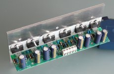
I've posted this before but here is said nasty chip amp running hard. As you can see it doesn't seem particularly bothered. At it's sweet spot of 40W, which is more than adequate for a lot of us it works very well. And is cheap to build and compact. It won't drive evil high end speakers, but for an active 2 way hard to do better in the same form factor.
Attachments

Last edited:
- Status
- Not open for further replies.
- Home
- Member Areas
- The Lounge
- John Curl's Blowtorch preamplifier part III