What voltage does the overload protection trip at when you power it from an adjustable supply? I've run these amps with 2R dummy loads in the past with no issues.
My bench supply is recently busted... Seems like every piece of equipment let me go recently... I have a new scope and now I need a new bench supply...
I've been trying to ramp up the voltage with my LM317K regulator. The source is a SMPS 12Vdc 2A and the LM can output 1.5A but I cannot seem to pass the 1.4Vdc on the output while connected to the current protection. This is a home made variable reg and I've ordered something much better for future use. It could be my reg that has issues... Without load I can go well over 5Vdc.
The current protection on controller PCB has pinout of + - + - if you look at the PCB with connector edge towards you, correct?
Thanks
Do
You have the pinout correct. Have you built the adjustable supply for TubSuMo? If so you can use it for testing your detection circuit. You can use a simple voltage divider on the output if the voltage range is too high to work with.
I think I have boards for a few different LM317 based regulators that work great for low current voltage sources for bench testing. I can send you one if you like.
I think I have boards for a few different LM317 based regulators that work great for low current voltage sources for bench testing. I can send you one if you like.
The current detection circuit hasn't been change since Valery's first version of the 21st Century control board other than the change to SMT resistors.
The forward voltage of the LEDs in the HCPL2530s can be quite different in different devices. This can cause the protection to trip at different currents in the output stage. This is why I like to measure the voltage that the protection trips at. I aim for 2.2V which translates to around 8A in the output pair or 24A total ( this is peak current, well within SOA of the device). Another thing that might influence the circuit operation is the emitter resistors selected for the amplifier. If they heat up quickly and their resistance rises the detection will trigger faster.
The forward voltage of the LEDs in the HCPL2530s can be quite different in different devices. This can cause the protection to trip at different currents in the output stage. This is why I like to measure the voltage that the protection trips at. I aim for 2.2V which translates to around 8A in the output pair or 24A total ( this is peak current, well within SOA of the device). Another thing that might influence the circuit operation is the emitter resistors selected for the amplifier. If they heat up quickly and their resistance rises the detection will trigger faster.
I’ve ordered a regulator board but will also assemble the one for the tubsumo filament supply for testing. The emitter resistor are good quality Ohmite Audio Gold non-inductive 5W. I touched them and they stay quite cool. I will look into the overload detection issue to find out the trigger voltage and report back. Worst case scenario we can adjust the resistors to match the proper trigger voltage.
Thanks
Do
Thanks
Do
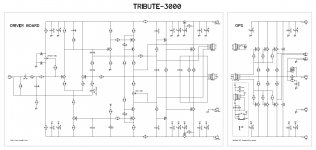
Tribute-3000 front-end (Driver board) standalone test
Hello All,
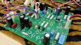
I have finally got some spare time for assembling and testing the 3000 Driver board.
Runs nicely from the first power-on, showing pretty solid performance with 10k temporary load
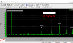
Spectrums are measured with 10V RMS at the output.
Started assembling the OPS board - the full-scale test is coming soon.
Cheers,
Valery
Hello All,
I have finally got some spare time for assembling and testing the 3000 Driver board.
Runs nicely from the first power-on, showing pretty solid performance with 10k temporary load
Spectrums are measured with 10V RMS at the output.
Started assembling the OPS board - the full-scale test is coming soon.
Cheers,
Valery
Attachments
-
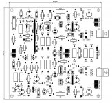 01-Tribute-3000-Silk.JPG149.8 KB · Views: 398
 -
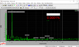 02 THD 01K.PNG46.6 KB · Views: 399
 -
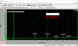 03 THD 10K.PNG45.5 KB · Views: 391
 -
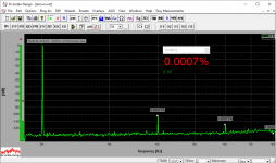 04 THD 20K.PNG40.2 KB · Views: 386
 -
 05 IMD 14-15K.PNG51.3 KB · Views: 385
 -
 IMG_20180313_130127.jpg144.5 KB · Views: 207
 -
 IMG_20180313_130109.jpg149.9 KB · Views: 185
 -
 IMG_20180313_123004.jpg107.1 KB · Views: 101
 -
 IMG_20180313_122839.jpg104.4 KB · Views: 94
 -
 IMG_20180313_122606.jpg104.1 KB · Views: 115
Good!Hello All,
I have finally got some spare time for assembling and testing the 3000 Driver board.
Runs nicely from the first power-on, showing pretty solid performance with 10k temporary load
Spectrums are measured with 10V RMS at the output.
Started assembling the OPS board - the full-scale test is coming soon.
Cheers,
Valery
Exactly what i'm looking for.

For the longest time I’ve been using my iPhone for signal generator since they have some great apps for it. Unfortunately, the iPhone sucks on square wave output... Is there a function/signal generator that is affordable and you would recommend?
There’s plenty of them on Amazon but don’t know if they’re good
Thanks
Do
There’s plenty of them on Amazon but don’t know if they’re good
Thanks
Do
For the longest time I’ve been using my iPhone for signal generator since they have some great apps for it. Unfortunately, the iPhone sucks on square wave output... Is there a function/signal generator that is affordable and you would recommend?
There’s plenty of them on Amazon but don’t know if they’re good
Thanks
Do
I have been using this one for a long time and have been happy with it.
BK Precision 3001 Audio Generator | eBay
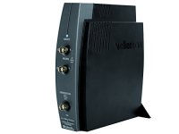
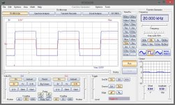
I use a Velleman PCSGU250 combo - a PC-based 2-channel oscilloscope + audio generator in one box.
It's handy for quick analysis of the circuit behavior.
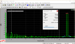
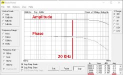
A cool feature, utilizing both scope channels and the generator - an automatic bode plotter, building the magnitude and phase responses on the same diagram within 100KHz or 1MHz bandwidth. Knowing the phase shift at 10-20KHz is useful (comments in red are added manually).
It has also got an FFT feature, although it's not as precise as a specialized audio analyzer - still good for quick assessment.
Here is what it looks like:
Velleman PCSGU250 Usb-Pc Scope + Generator (2Ch.): Science Lab Oscilloscopes: Amazon.com: Industrial & Scientific
Cheers,
Valery
It's handy for quick analysis of the circuit behavior.
A cool feature, utilizing both scope channels and the generator - an automatic bode plotter, building the magnitude and phase responses on the same diagram within 100KHz or 1MHz bandwidth. Knowing the phase shift at 10-20KHz is useful (comments in red are added manually).
It has also got an FFT feature, although it's not as precise as a specialized audio analyzer - still good for quick assessment.
Here is what it looks like:
Velleman PCSGU250 Usb-Pc Scope + Generator (2Ch.): Science Lab Oscilloscopes: Amazon.com: Industrial & Scientific
Cheers,
Valery
Attachments
Last edited:
Valery
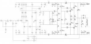
Some time ago you suggested a Luxman-inspired front-end that could be used with your output board mosfet designs, which I think might be fine idea.
Would it be something like this? I just joined the schematics, so what would you change?
The Luxman model I think you are talking about is the M-02, right?
Attachments
Valery
Some time ago you suggested a Luxman-inspired front-end that could be used with your output board mosfet designs, which I think might be fine idea.
Would it be something like this? I just joined the schematics, so what would you change?
The Luxman model I think you are talking about is the M-02, right?
Hi,
I don't remember exactly what model it was, M-02 - could be.
jFET IPS, followed by a folded cascode is an excellent combination in my opinion.
The overall schematic looks good, I will try to run a few tests in the sim over the weekend.
Cheers,
Valery
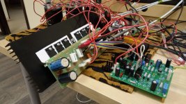
Full prototype test
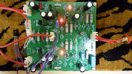
Finally - a quick test of the whole Tribute-3000 amplifier.
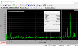
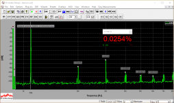
The harmonic profile - H3 dominates, however, the profile is rather short (no high-order components), mostly conditioned by the OPS.
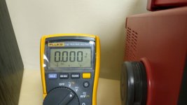
Voltmeter shows DC offset at the output - very stable, staying within +/-1mV.
A very fine amplifier with solid bass, detailed mids, maybe a bit more accented highs than I normally prefer - particularly comparing to ODNF amplifier (auditioned with the same pair of speakers). At the same time, this one is capable of driving rather "difficult" loads, providing the output current high enough when required. Very low noise.
I used 2sc5200/a1943 Toshiba output devices from my stock in this build.
The amplifier is easy to build - my prototype started up at the first power on with no issues. The quiescent current of the outputs is set to 70mA per pair at idle.
Cheers,
Valery
Finally - a quick test of the whole Tribute-3000 amplifier.
The harmonic profile - H3 dominates, however, the profile is rather short (no high-order components), mostly conditioned by the OPS.
Voltmeter shows DC offset at the output - very stable, staying within +/-1mV.
A very fine amplifier with solid bass, detailed mids, maybe a bit more accented highs than I normally prefer - particularly comparing to ODNF amplifier (auditioned with the same pair of speakers). At the same time, this one is capable of driving rather "difficult" loads, providing the output current high enough when required. Very low noise.
I used 2sc5200/a1943 Toshiba output devices from my stock in this build.
The amplifier is easy to build - my prototype started up at the first power on with no issues. The quiescent current of the outputs is set to 70mA per pair at idle.
Cheers,
Valery
Attachments
-
 IMG_20180316_184717.jpg140.6 KB · Views: 228
 -
 05 IMD 14-15K.PNG52.2 KB · Views: 140
 -
 04 THD 20K.PNG45.4 KB · Views: 134
 -
 03 THD 10K.PNG47.3 KB · Views: 146
 -
 02 THD 01K.PNG51.3 KB · Views: 160
 -
 01 IMG_20180316_180847.jpg64.8 KB · Views: 138
 -
 01 IMG_20180316_180738.jpg100.3 KB · Views: 422
 -
 01 IMG_20180316_180648.png876.9 KB · Views: 454
 -
 01 IMG_20180316_180634.jpg101.6 KB · Views: 509
 -
 00 Tribute-3000 Sch.JPG148.9 KB · Views: 532
TESTED!Finally - a quick test of the whole Tribute-3000 amplifier.
The harmonic profile - H3 dominates, however, the profile is rather short (no high-order components), mostly conditioned by the OPS.
Voltmeter shows DC offset at the output - very stable, staying within +/-1mV.
A very fine amplifier with solid bass, detailed mids, maybe a bit more accented highs than I normally prefer - particularly comparing to ODNF amplifier (auditioned with the same pair of speakers). At the same time, this one is capable of driving rather "difficult" loads, providing the output current high enough when required. Very low noise.
I used 2sc5200/a1943 Toshiba output devices from my stock in this build.
The amplifier is easy to build - my prototype started up at the first power on with no issues. The quiescent current of the outputs is set to 70mA per pair at idle.
Cheers,
Valery

Tribute-3000 spectrums
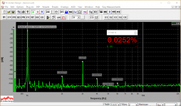
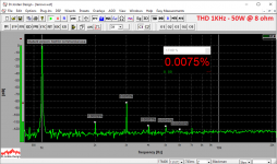
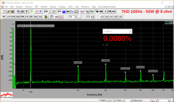
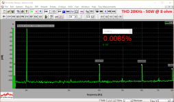
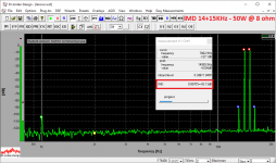
More precise spectrums. Previous quick measurements were taken on the edge of overload at the input of the audio analyzer. Correct attenuation results in more accurate measurements. Output swing is 20V RMS @ 8 ohm load.
A very fine amplifier.
More precise spectrums. Previous quick measurements were taken on the edge of overload at the input of the audio analyzer. Correct attenuation results in more accurate measurements. Output swing is 20V RMS @ 8 ohm load.
A very fine amplifier.
Attachments
The current detection circuit hasn't been change since Valery's first version of the 21st Century control board other than the change to SMT resistors.
The forward voltage of the LEDs in the HCPL2530s can be quite different in different devices. This can cause the protection to trip at different currents in the output stage. This is why I like to measure the voltage that the protection trips at. I aim for 2.2V which translates to around 8A in the output pair or 24A total ( this is peak current, well within SOA of the device). Another thing that might influence the circuit operation is the emitter resistors selected for the amplifier. If they heat up quickly and their resistance rises the detection will trigger faster.
Hi Jeff,
I bought a variable power supply that has CC and has fine voltage adjustment. There's an LCD on it for input voltage and current as well for output. I also connected my multimeter to make sure the output voltage matched the LCD of the DC-DC converter. Increased the voltage on the OC protection (left side) until it triggered. I was reading about 1.98Vdc when it triggered and 2.0Vdc for the right side. I don't know what it translate into as far as current goes. My DC-DC converter has a button to disable the output load on the fly. I turned it off, set the output voltage to 1Vdc and turned it on momentarily and the amp went into OCP right away. Could it be that it is very sensitive?
I will also measure the voltage from the OC output on the amp module when it is connected to a speaker load and playing music to see what voltage I'm getting from each amp before it triggers.
Thanks
Do
It sounds too sensitive. Try raising the resistance of R7/10 to get trip voltage closer to 2.2V. If it's still too sensitive at that voltage replace C12 with a 0.1uF cap. This will slow activation time slightly but there may be some external noise on the digital line possibly causing a hair trigger like the voltage loss detection circuit was seeing. I haven't run this board in a complete chassis for an extended period yet so I'm not sure if it has any glitches to iron out but it sounds pretty quick to trigger.
I connected 2x 8R 50W resistors in parallel on the output and played music through my iPhone up to max level (which is roughly 1V output) and both modules could take it without any issues. Protection did not trigger. Could I put a cap across the resistors load to simulate a much harder load? If yes, what value would you recommend?
I also just finished grounding the whole chassis but the amplifier PSUs are left floating for now.
What resistor values would you suggest to replace (or piggy back) to get to 2.2V?
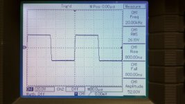
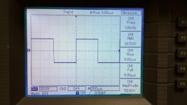
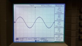
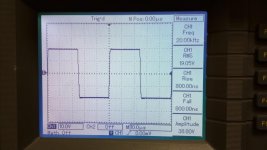
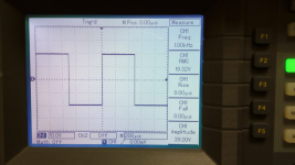
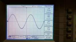
I will also try some sinus and square wave @ 1KHz, 10KHz and 20KHz and see the behavior. But so far the amplifiers seem to be working properly with no signs of oscillation as I can tell.
Thanks
Do
I also just finished grounding the whole chassis but the amplifier PSUs are left floating for now.
What resistor values would you suggest to replace (or piggy back) to get to 2.2V?
I will also try some sinus and square wave @ 1KHz, 10KHz and 20KHz and see the behavior. But so far the amplifiers seem to be working properly with no signs of oscillation as I can tell.
Thanks
Do
- Home
- Amplifiers
- Solid State
- Revisiting some "old" ideas from 1970's - IPS, OPS