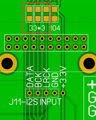
Using J11 to connect the raspberry pi, you need to remove three 33 ohm resistors. This way, the i2s is the raspberry pie, but the hdmi i2s isn't available.
View attachment 619601
@audiozen,
that's what I thought. Will do so, thanks! For future use, I think I make it internally switchable.
I need some explanation here:
I understand that 2 sources of I2s are supported currently by AZ board as Soekris is prepared for it. So they are:
1. Amanero USB to I2S
2. HDMI for Direct I2S?
Is there any digital switch which differentiate them for Soekris?
Is it visible on display?
Second topic:
I am going to create external on/of switch for choosing the input between Raspbery Pi (or Tinker Board) and HDMI. I want to still keep functional HDMI(I2s) as is now, just to have possibility to switch manually to RBPi. Should I brake/cut PCB paths between I2S and resistors? .
Which paths I need to cut? All of them or it is enough to cut GND and 3,3V? Or perhaps can I connect RPi directly to isolated I2S input on Soekris? And leave this HDMI as is?
I really appreciate your support but...As mentioned goal is to connect 3 sources to 2 inputs. I don't want to dismantle/deactivate HDMI (remain used by external transport) and sometime I will use Amanero for my PC (resistors I guess should remain in such case?) . Should be HDMI or Amanero switchable witth this RPi?The HDMI interface of AZ1021 SK is a differential I2S signal, and the interface standard is the same as PS audio
If you don't want to use this HDMI, you can remove the 3 resistors in the red box. Then J11 of AZ1021 SK is the second standard I2S interface.
Could you elaborate on this in free moment? Thank you
Last edited:
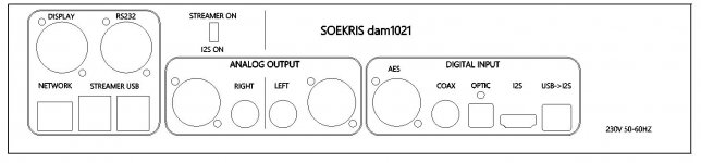
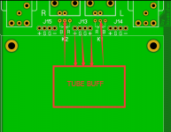
Thank you for drawing I used it to create own version for 320*70mm . Here is my multilayer CAD draw(so simply switch off measurements or print layer if openings are needed only).Since the chassis has not been progressed, so I put the back panel files of the chassis for reference.
I decided to buy ready full aluminium case WA50 -you can find it ie on eBay as it already has big windows in the front and 2 knobs (transparent screen is attached).
I used opportunity to utilize additional space and added Raspbery Pi /Tinker Board section with switch between I2S (HDMI) and RPi.
Additional socket holes are standard Neutik D type.
Attachments
Last edited:
J11 and HDMI can only use one. When the resistances are removed, HDMI can't be used.
I think there is misunderstanding between us. I won't use both inputs in same time, but find the best way to manually switch between them. So I2S or RPi manual switch is something I need.I asked you for the support as you know it better. thanx
I ordered the AZ1021 (non-lite). Is it possible to to build a tube buffer using the signal off j13? If so, what would you recommend for hooking up RCAs (I only will use the DAC single ended). I could leave the board intact and add a another RCA set or remove the RCAs from the board and use them. Any other ideas/thoughts?
Thank you for drawing I used it to create own version for 320*70mm . Here is my multilayer CAD draw(so simply switch off measurements or print layer if openings are needed only).
I decided to buy ready full aluminium case WA50 -you can find it ie on eBay as it already has big windows in the front and 2 knobs (transparent screen is attached).
I used opportunity to utilize additional space and added Raspbery Pi /Tinker Board section with switch between I2S (HDMI) and RPi.
Additional socket holes are standard Neutik D type.
The analog output L R needs to be changed.
L change to R,and R change to L.
Thank you for the hint!The analog output L R needs to be changed.
L change to R,and R change to L.
I will paste update as soon I will have it
- Home
- Vendor's Bazaar
- AZ OLED setup kits for Soekris dam1021/1121 control