Sorry, our responses are wrong, maybe because of a language barrier.
I am not a native speaker myself.
Again, this is the situation: I have one board with connections to
three transformer secondary windings: If Dac and Output stage are powered,
the DAC is complety quiet. I can pull the volume of my amplifier all way up and hear nothing.
When the clock (the third circuit) is powered up , a hum is audible, something between-80db.
Sounds like an open ground loop. That is the whole story.
I did not conclude at all that a single chip introduces the hum.
I assume that the complete clock circuitry introduces the hum and think it might be a problem of grounding. Nothing more.
I did also describe that I did only power Clock and Output stage - the hum is even louder. Clock and output stage
are on the opposite sides of the board. So I again assume that this might be a problem of how the ground plane was
designed or connected internally.
As clock and Dac are both running from 9VAC, I did also this test:
Remove the voltage regulator of the clock´s supply circuit and feed both, DAC and Clock from the DACs voltage regulator.
This also made the hum louder.
So I again assume the rground planes of clock and Dac circutry do interact in a negative way.
And maybe they must be completely seperated (or connected at points other than the default connections)
All the best,
Salar
Last edited:
Unfortunately the test with a battery killed the board 
The schematic states the regulators are LM7805 - but it is LT1086 with different
pin-connections. So I put 9V to GND and Vout. Changed the regulators after the mishap, but they do not seem to be affected.
Voltages are there but no lock and no sound. The heatsinks of the regulators stay cold...
The schematic states the regulators are LM7805 - but it is LT1086 with different
pin-connections. So I put 9V to GND and Vout. Changed the regulators after the mishap, but they do not seem to be affected.
Voltages are there but no lock and no sound. The heatsinks of the regulators stay cold...
If I was you I would use a tone which is more friendly. I did connect a 9V battery
directly to the voltage regulator (LT1086) bypassing the rectifier.
Schematic says it is 78xx types with ordinary pinout which is wrong.
So, wrong cabling. My fault. I did not take CON3 as a literal instruction.
"making clear" defines to me to explain, i.e. "simply put the battery before rectification".
Thank you for your support. One very basic question:
After the mishap, CON2 and 3. I still measure the correct voltages in the circuitry connected to CON2 and CON3 - with the LT1086 as well as with the
their following regulators that provide the final voltages of 3.3V and 1.2 V.
But the LT1086 regulators do not get warm at all.
Before the "battery accident", their heatsinks got hot as regular.
So a very basic question (too basic to google)
If a regulator gives a correct output voltage, but does not get warm- does this mean that there is no load at all, i.e. the ES9018 is dead?
All the best,
Salar
Let me resurrect this thread.
I am in a very slow process of building ESS9018 dac.
I have written in up here:
Slow construction of ESS9018 dac
The reason for this post is a question about AVCC regulator which stopped working.
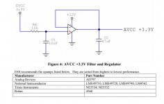
I my never ending tweaking phase (gremlins whisper in my ear I can make it even better) I tried separate 3.3V DVCC and AVCC using two LT3045. I tried also multistage regulators one LM317 (regulating to 5.5V) and then two ADP151 regulating to 3.3V. DVCC is taken from one ADP151 directly while
the other 3.3V is used a reference for the op amp buffer as suggested by ESS (see attached picture). The capacitances are like in the pic. The only diff is that the VCC for the opamp (lm49710) is 5.5V coming from the first stage of regulation.
Well it worked fine until I decided to put LT3042 instead adp151 to provide 3.3V reference.
Now I have 3.3V coming from opamp but only with light loads. With the dac attached output of the opamp drops to some 2.7V which I also see at the inverting input. The noninverting input is nicely at 3.3V. I really do not understand. Have I zipped the opamp?
Before you ask: the dac is fine all works fine (with the opamp regulator)
I am in a very slow process of building ESS9018 dac.
I have written in up here:
Slow construction of ESS9018 dac
The reason for this post is a question about AVCC regulator which stopped working.
I my never ending tweaking phase (gremlins whisper in my ear I can make it even better) I tried separate 3.3V DVCC and AVCC using two LT3045. I tried also multistage regulators one LM317 (regulating to 5.5V) and then two ADP151 regulating to 3.3V. DVCC is taken from one ADP151 directly while
the other 3.3V is used a reference for the op amp buffer as suggested by ESS (see attached picture). The capacitances are like in the pic. The only diff is that the VCC for the opamp (lm49710) is 5.5V coming from the first stage of regulation.
Well it worked fine until I decided to put LT3042 instead adp151 to provide 3.3V reference.
Now I have 3.3V coming from opamp but only with light loads. With the dac attached output of the opamp drops to some 2.7V which I also see at the inverting input. The noninverting input is nicely at 3.3V. I really do not understand. Have I zipped the opamp?
Before you ask: the dac is fine all works fine (with the opamp regulator)
Attachments
- Status
- This old topic is closed. If you want to reopen this topic, contact a moderator using the "Report Post" button.
- Home
- Source & Line
- Digital Line Level
- DIY ES9018 Hi-end USB DAC