Background: I have a single-ended pentode amplifier with adjustable fixed bias. It's a simple circuit with 5687 driver in cascade, 100K grid leak resistor on the grid of the output tube. Screen voltage is regulated with two VR tubes, making ~250V. Bias supply is the classic half-wave RC filtered with potentiometers. For fun I also included a banana socket that is tied to pin three of the output tube - with the idea I can roll in plate cap tubes like the EL38, 12E1, TT21, etc etc without doing any rewiring - just plug in a banana jack attached to a length of wire and a plate cap.
KT88s, 6550s, EL34s, KT77s, 6L6GCs, etc work no problem at all. I can adjust the bias so a KT88, for example, can draw 0mA or all the way beyond the 100mA meter range.
But when I plug in ITT/STC labeled 12E1s with a plate cap, even with the bias controls turned all the way down, the current runs away as the filaments start glowing, eventually swinging beyond 100mA on both meters. The VR tubes also never start glowing, indicating enough load on the power supply that the gas tubes aren't striking. I immediately shut down the amp at this point for fear of popping a fuse or the 10 ohm cathode resistors on the output tubes.
This experiment was last night so I haven't started really digging yet but so far I'm not seeing any pin differences - except for the obvious plate cap - between the 12E1 and a "common" audio tube. Any pointers would be greatly appreciated - I'm already not looking forward to moving this little tank off of the shelf.
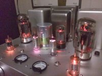
Picture is to give you some idea of the amplifier setup.
KT88s, 6550s, EL34s, KT77s, 6L6GCs, etc work no problem at all. I can adjust the bias so a KT88, for example, can draw 0mA or all the way beyond the 100mA meter range.
But when I plug in ITT/STC labeled 12E1s with a plate cap, even with the bias controls turned all the way down, the current runs away as the filaments start glowing, eventually swinging beyond 100mA on both meters. The VR tubes also never start glowing, indicating enough load on the power supply that the gas tubes aren't striking. I immediately shut down the amp at this point for fear of popping a fuse or the 10 ohm cathode resistors on the output tubes.
This experiment was last night so I haven't started really digging yet but so far I'm not seeing any pin differences - except for the obvious plate cap - between the 12E1 and a "common" audio tube. Any pointers would be greatly appreciated - I'm already not looking forward to moving this little tank off of the shelf.
Picture is to give you some idea of the amplifier setup.
Attachments
Patient: Doctor when I do this it hurts.
Doctor: Don't do that!
Amateur here so take this with a grain of salt. Were the inputs shorted? Were you getting signal at this point. I was recently working on my Mark VI's and I replaced the original feedback circuit. When I turned the amp on the first time I had the same problem. Turned out the feedback caused a powerful oscillation that was driving the amp without any signal. What kind of feedback are you running?
Also, One of the 12E1 data sheets I found lists maximum of 200 ma? Damn! It also lists maximum grid bias voltage at -100 do you have that much available?
Last edited:
Did you verify that the tube is good? Patrick Turner mentioned he got some bad NOS 13E1s right out the box even if they looked perfectly good.
I'm starting to lean that way - will see if my Sencore tester has settings for a 12E1 (doubtful).
The curves are not clear on my mobile, but it is probably doing what it is supposed to do.
It most likely needs lots more negative volts on g1 than the other types you have tried.
It is a series regulator after all.
I made that mistake once with a 6c19 (before there were online spec sheets): it's the size of an EL84, so let's try it in an amp. I didn't know that at 300V it would need 10x more neg
Amateur here so take this with a grain of salt. Were the inputs shorted? Were you getting signal at this point.
Also, One of the 12E1 data sheets I found lists maximum of 200 ma? Damn! It also lists maximum grid bias voltage at -100 do you have that much available?
I immediately replaced the 12E1s/plate caps with KT88s and the amplifier returned to normal operation... after dialing in the bias I went back to listening to music while doing some *ahem* real job work.
Don't remember the exact max bias voltage, but it's around negative 60VDC.
My thinking so far: it appears to have something to do with the 12E1 tubes themselves; either they're both gassy, the design of this valve doesn't "like" fixed bias, the 100K grid leak resistor is too high, or there is some internal connection on pin 3 that isn't listed on the tube spec.
edit: or as Parafeed said above, I don't have enough available negative voltage. Will look at the curves again... sure wish I could find a "typical" operation point as an amplifier, but being regulator tubes they kind of skipped this part.
Circuit is _simple_ - can be found here
6th Street Bridge: Project: Mult-Valve: The Universal Pentode Amplifier
Last edited:
I think it's fairly unlikely that you have two faulty 12e1s. The STC/ITT ones are pretty good quality. I once found one with an intermittent heater due to a poor connection with the base but all the rest have been perfect.
12E1s do like to oscillate and they will draw lots of current if this is happening. My amp needs 120R grid and screen stoppers to discourage it from turning into a radio transmitter.
I have had no luck getting them to work with fixed bias. Any time I have tried them like this I couldn't get the plate current to stabilise as they seemed to be drawing current from the bias supply so that the voltage dropped (Impossible, I know.. I'm sure someone will have a logical explanation)
The 12E1 is a different sort of tube from the KT88, 6L6 etc and in my opinion, works better with lower voltages and more current. My amp uses them in SE at 300v and around 85mA with a 2.5K transformer. Driver stage is EF37 / 6SN7 copied from Pete Millett's 829B amplifier. Using big horns so don't need much power.
You said the screen voltage is nominally 250V, but what is the anode supply voltage? Also, what is the range of the bias supply? Does it go to -100V or something?
Oscillation does seem likely. That top-cap lead is going have plenty of inductance. Stopper resistors and possibly a ferrite ring around the cathode lead would be sensible additions.
Oscillation does seem likely. That top-cap lead is going have plenty of inductance. Stopper resistors and possibly a ferrite ring around the cathode lead would be sensible additions.
Last edited:
If you use a 12E1 valve, the screen voltage should be 150V maximum, as the valve is very sensitive, and can easily pull 300mA with just 150V on the screen. For tetrode S-E class A, try -15V on the grid for around 85mA plate current.
-15v on the grid? - that would result in high current flow. As commented earlier in this thread, the 12E1 likes to work with quite large negative grid voltages.
Seems it's an old thread but sounds interesting. A couple years ago I have tested a pair of 12E1 in PP pentode mode.
The parameters of the set up were: Vplate=620V, Vg2=300, Iplate(0sig)=50mA unfortunately I have not kept a note of the Vg1 but I could have control over the plate current. I think it needed more than -50V to keep the plate current at a safe value. The amp was able to produce 100W . The P-P load was 6.8k . I have also added a 10R stopper resistor on each plate and 470R on each g2. Observing the output on a scope it showed no parasitic oscillations at all.
The parameters of the set up were: Vplate=620V, Vg2=300, Iplate(0sig)=50mA unfortunately I have not kept a note of the Vg1 but I could have control over the plate current. I think it needed more than -50V to keep the plate current at a safe value. The amp was able to produce 100W . The P-P load was 6.8k . I have also added a 10R stopper resistor on each plate and 470R on each g2. Observing the output on a scope it showed no parasitic oscillations at all.
- Home
- Amplifiers
- Tubes / Valves
- 12E1 in fixed bias - too much current!