Hello All.
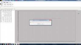
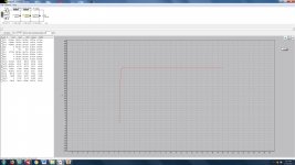
I would like to build a choke input power supply for a 300B project that I am working on. I will be building dual mono power supplies on one chassis dedicated to just the B+ and DC filament supplies. This supply will use 2 large Freed power transformers with 520-0-520 volts at 250 mA and 375-0 volts at 35 mA secondaries on each transformer. This would appear to be overkill, but I have them on hand. I figure that I can use the 520 for the 300B B+ and the 375 for the pre tube B+. I was hoping to use a choke input filter to bring the voltages down to around a 420-430 volts B+, and was playing with PSUD-II to figure out what that looks like. The 4 chokes I have at hand are all the same, and are very large and heavy. They are vintage, and I can't find any info on them based on their markings, but they appear to be quality swinging chokes. They measure 54 Ohms and 8.43 Henries on my multimeter. I have built many capacitor input supplies, and modeled them on PSUD II without issue, but never a choke input supply. I have attached a PSUD II simulation that is not the usual quick rise and wiggle free curve that I'm used to. Obviously I'm missing some important component here. There is no way that the result in the screenshot is a desirable one. I know that voltages are too high, but I used a very low drop rectifier in the example, and can switch it to another. I hope to run the 300Bs at 350-360 volts plate to cathode, and at -75 volts on the cathode for a total of around 425-435 volts (50-60 mA), and would like to use the components that I have at hand. Any advice or references that will explain what is going on, and how to fix, it would be very appreciated.
I would like to build a choke input power supply for a 300B project that I am working on. I will be building dual mono power supplies on one chassis dedicated to just the B+ and DC filament supplies. This supply will use 2 large Freed power transformers with 520-0-520 volts at 250 mA and 375-0 volts at 35 mA secondaries on each transformer. This would appear to be overkill, but I have them on hand. I figure that I can use the 520 for the 300B B+ and the 375 for the pre tube B+. I was hoping to use a choke input filter to bring the voltages down to around a 420-430 volts B+, and was playing with PSUD-II to figure out what that looks like. The 4 chokes I have at hand are all the same, and are very large and heavy. They are vintage, and I can't find any info on them based on their markings, but they appear to be quality swinging chokes. They measure 54 Ohms and 8.43 Henries on my multimeter. I have built many capacitor input supplies, and modeled them on PSUD II without issue, but never a choke input supply. I have attached a PSUD II simulation that is not the usual quick rise and wiggle free curve that I'm used to. Obviously I'm missing some important component here. There is no way that the result in the screenshot is a desirable one. I know that voltages are too high, but I used a very low drop rectifier in the example, and can switch it to another. I hope to run the 300Bs at 350-360 volts plate to cathode, and at -75 volts on the cathode for a total of around 425-435 volts (50-60 mA), and would like to use the components that I have at hand. Any advice or references that will explain what is going on, and how to fix, it would be very appreciated.
Attachments
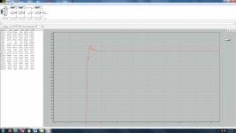
Not exactly my realm but I will guess that the wiggles are not 100Hz charging artefacts.
Calculate the characteristic LC section impedances as SQRT(L/C). For example...
SQRT(8H43/100uF) = 290R
In the above case you already have 54R from the Choke winding resistance so for 'critical' damping or concept thereof you need to add about 240R.
Put another electrolytic capacitor about 3 times the original, 330uF, in series with a 240R resistor in parallel with your original 100uF.
Do the same on the second section and then on the final section...
SQRT(30H/47uF) = 799R - 595R = 200R with 150uF.
Hopefully that will either get rid of or otherwise tame the wiggles.
Oh... you do not get quick rises because you have big inductors. 8H43 and 100uF is at about 5Hz so guess your rise time would be about 200mS or longer.
Last edited:
Are you going to use an indirectly heated valve rectifier as a means to minimise the initial voltage overshoot, or does the 300B start to conduct fast enough to load the power supply with a directly heated valve rectifier? PSUD2 can sort of show that risk by using a stepped constant current load with an initial vary low current level. I don't use 300B's so unsure of that performance.
PSUD2 can be used to assess ringing response to load transients by introducing a step change in constant current load from say idle load current to twice that value at a time when everything is operating steady-state (eg. after 1 sec). Your filter doesn't show any significant ringing when I sim it - mainly due to the significant choke DCR levels.
Power on oscillatory response from mains charging pulses is not likely to be an issue at all - and caution is required in viewing the sim waveform during that initial period as there are many non-linear processes going on that aren't properly modelled in a sim (loading resistance change; inductor inductance due to DC current change, diode resistance change due to heater warming up).
The sim also has a hard time with diode turn-off and on transitions due to the choke current - so caution is required in assessing any such sim waveforms. That's not to say that circuit design and layout should not worry choke input formats - as that format has large dI/dt transients - and so best to use tuned snubbers on the PT secondary windings (as per Quasimodo), and a small bypass cap on the output of the diodes to steer transient current back through the choke current loop.
Your supply could also use protection ss diodes in series with valve anodes, and a CT fuse, as there is a lot of grunt available.
Last edited:
updated choke input sim
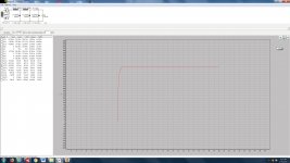
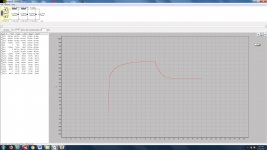
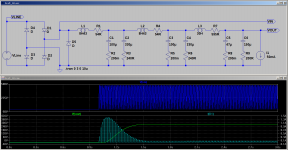
Thanks MorbidFractal for your suggestions. I realized that I would be feeding the preamp tube from a separate winding, so I removed it from the sim. I put in values for the capacitors that reflect what I have at hand, and that would stand up to the voltages required at each position. It appears that the result, according to PSUD II, is in line with what I'm used to seeing in my capacitor input sims, although I didn't put in as much capacitance as suggested by the equation. The rise time improves with the decrease in capacitance, and there is no sign of the wiggles with the sim as is. Is this an indication that all is good, or am I missing something? I have attached a few photos of the sim. There is an issue with exceeding the PIV of the rectifier, an 83, that comes up in the sim as well. Is there a workaround for this, or will it be okay because the operating conditions after initial startup are well within the capabilities of the 83 tubes? Thanks for the help with this! It is much appreciated.
Thanks MorbidFractal for your suggestions. I realized that I would be feeding the preamp tube from a separate winding, so I removed it from the sim. I put in values for the capacitors that reflect what I have at hand, and that would stand up to the voltages required at each position. It appears that the result, according to PSUD II, is in line with what I'm used to seeing in my capacitor input sims, although I didn't put in as much capacitance as suggested by the equation. The rise time improves with the decrease in capacitance, and there is no sign of the wiggles with the sim as is. Is this an indication that all is good, or am I missing something? I have attached a few photos of the sim. There is an issue with exceeding the PIV of the rectifier, an 83, that comes up in the sim as well. Is there a workaround for this, or will it be okay because the operating conditions after initial startup are well within the capabilities of the 83 tubes? Thanks for the help with this! It is much appreciated.
Attachments
I missed the last two responses while putting together the above post.
MorbidFractal: I'm not sure what you mean by putting the first damping section at the beginning. Does that mean putting the parallel capacitor and resistor in front of the first inductor? Doesn't that make it a capacitor input filter?
trobbins: Do you mean that I don't need to worry about the wiggles in the first photo, and that the supply is actually okay? I have a fairly good selection of rectifier tubes, and can use whatever is appropriate. I would prefer a 5 volt tube, and I have several 80s and 83s handy should I want to drop the voltage somewhat for a different circuit or operating point. It appears that I get the error message no matter what rectifier tube I use. I will try the stepped response with the original sim in my first post.
Yes I suggest you don't worry about charging wiggles in your situation.
You may get some initial B+ voltage overshoot with directly heated diodes, but it sounds like you are putting in caps that would manage 800VDC surge.
Have a look at the diode PIV in the sim waveforms - they are about 1600V - you have chosen a 1400V PIV diode - can you see that spec in the diode data sheet? Either use a diode with at least 1600V PIV or slightly cheat and add seriesed ss diodes in series with each valve diode plate.
Your sim shows strange capacitor ESR values??
choke input sim
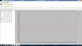
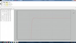
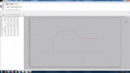
I tried two sims with stepped response. One with a 240 Ohm resistor in parallel with each of the original's first two 100uF capacitors, and one without them in place. It appears that there is a small wobble on the stepped response when there are no resistors in place, and no wobble with the resistors in place. There is still an issue with the PIV being exceeded of any rectifier that I have at hand. I have attached some more photos.
I tried two sims with stepped response. One with a 240 Ohm resistor in parallel with each of the original's first two 100uF capacitors, and one without them in place. It appears that there is a small wobble on the stepped response when there are no resistors in place, and no wobble with the resistors in place. There is still an issue with the PIV being exceeded of any rectifier that I have at hand. I have attached some more photos.
Attachments
The capacitor ESR values (240 Ohms) were my way of showing a parallel resistor to the capacitor of 240 Ohms, as per MorbidFractal's suggestion. I'm not sure if that is the correct way of doing it, but there doesn't appear to be any other way of showing parallel resistance in PSUD II. Is there a proper way to do it?
Agreed - you need to use a different diode (eg. 5R4) or do the ss diode short-cut.There is still an issue with the PIV being exceeded of any rectifier that I have at hand.
That is the wrong way to sim a parallel resistance - there is no way to do it in PSUD2 (perhaps PSUD3 will provide that capability).
Last edited:
trobbins: Thanks for clarifying that. Is there a benefit to adding the parallel resistance as suggested by MorbidFractal? if I put ss diodes in series with the valve diode plate, will that allow mw to use any tube rectifier? I read somewhere that I could use a few zeners strung together in series to limit the voltage or current to the first filter stage. From what I recall, the total added voltage of the zeners should be above the total steady state voltage of the power supply. Is this correct?
It's not easy to determine appropriate dampening for power supply LCLC type filters, because one end is receiving charging pulses, and the other end is sort of resistively loaded (an output stage is not a resistor or a constant current with respect to music signal transient loading). I suggest the stepped constant current load technique for PSUD2 is about as good an indicator as any - and I don't see your circuit ringing in my sim.
The short-cut method to raise valve PIV requires caution, as there are many ways a diode could have problems with PIV stress - so its only a short-cut to raise the PIV 'a bit', say from 1400V to 1600V. The ss diodes have to be similarly rated, so 3 1N4007 in series (with those diodes from the same batch) would be appropriate.
Using zeners to drop voltage is starting to raise queries as to why you need to drop voltage, and how does your amp cope with typical +/- 5 to 10% mains voltage variation.
It seems that I should pick a more appropriate pair of transformers that better suit the circuit that I want to build, or use one of the larger single transformers instead. Trying to get 525-0-525 to work is causing problems and complicating things due to the voltage being too high (even though I have 5 of these transformers!). I also have nice quad of 300-0-300, and several large single 375-0-375 transformers.
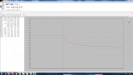
Ooooops. My bad. Perhaps I did not explain things so well. See the attached which shows the additional damping.
Your over-voltage on the rectifier diodes is ocurring because at some point they go open circuit whilst your input inductor is still trying to draw current. I've added a diode, catch, to overcome that problem.
You also have to consider the nature of the input voltage. If your filter had an input capacitor then that would charge to the peak line input voltage and you would expect the output voltage to reach a similar value.
In your case the input is an inductor and, with the catch diode in place the voltage is a full wave rectified sine. Your filter acts to average that voltage,
Average and effective values :: Electronic Measurements
VAV = Vpk x 0.637
In my model 480 x 0.637 = 305V but you lose 35 volts due to your 50mA load current and resistance in the inductors to end up with about 270V.
Attachments
A standard uncontrolled diode bridge inherently includes a catch (or free-wheeling) diode - not sure why an additional diode would be needed for this application?
I should admit to being slightly in the dark in respect of that one. I am used to things like a push-pull supply whereby during inductor reset both rectifier diodes are forced to conduct and carry the free-wheeling current. I suppose that should be the case here.
I note you are slightly wary about simulation results and possibly rightly so. It could be the case that the simulation loses the plot at that point and reports a false answer...
Either way the additional diode, D5, makes the apparent problem go away. I would be inclined to put it in for peace of mind.
DC output voltage is circa 0.9 x Vac(rms) of active winding for a choke input filter.
Indeed... 0.9/SQRT(2) = 0.636 It is just a different but less precise way of expressing things. 2/PI = 0.637.
The important thing is that the filter averages its input voltage. As such although the value is more or less right the inclusion of (rms) might be slightly confusing.
Simulation has a hard time converging on the next calculated value when any step or rapid change occurs - that often occurs when inductor current has to commutate between different diodes, and can cause humongous voltage spikes to show up. Adding a few other parts around the step can help the simulation. Be wary not to read too much in to sim results if you haven't experienced the waveforms in real circuits.
Choke input filters have a much easier time with valve diodes, as the commutation process is relatively slow and damped by the diode resistance. Not so easy for ss diodes due to the abruptness of the turn-on and off.
Choke input filters have a much easier time with valve diodes, as the commutation process is relatively slow and damped by the diode resistance. Not so easy for ss diodes due to the abruptness of the turn-on and off.
Thanks for the input, references and the sim. My primary concern is with the PIV of the tube rectifier being exceeded. I would like to use one of the many regular rectifiers that I own. Assuming that I use the 520-0-520 volt transformers, and that I want to operate at 350-360 plate to cathode and around 50 mA (-75 volts), for a total of 425-435 volts, it would appear that a rectifier that has a big voltage drop would be better than adding resistance in series to achieve that drop. In PSUD II there is no rectifier that I have in inventory that doesn't have it's PIV exceeded. it would appear, if I'm reading this list right, http://www.fourwater.com/files/fullrect.txt
that there are only a few tube rectifiers that can handle a 520-0-520 transformer voltage.
MorbidFractal: Are you saying that D5 solves the PIV problem for rectifiers?
trobbins: Are you saying that I don't have to worry about the PIV issue because the sims are wrong about it being a problem?
Sorry if these are dumb questions, but I am a choke input virgin.
Post #12 is my view regarding PIV. PIV is a concern if you exceed the rated spec. A sim just helps identify what PIV level you are likely to get - although the diode datasheets also usually show what Vac can be handled and still be within PIV spec. The linked article has some more PIV discussion, especially if you want to use ss diodes to help protect a valve diode:
https://www.dalmura.com.au/static/Power%20supply%20issues%20for%20tube%20amps.pdf
If you have excess B+ for your output stage, then you could consider using backbias to transfer some of the available B+ in to bias voltage. Backbias isn't used much - perhaps the most informative on-line discussion is by Elliot.
Last edited:
- Status
- This old topic is closed. If you want to reopen this topic, contact a moderator using the "Report Post" button.
- Home
- Amplifiers
- Power Supplies
- choke input power supply question