Karl, thank you for all your efforts and useful links. All in all, it is not perfectly developed and tested fit and forget project as it is. Too much on the cutting edge.
A little harsh, I'm no electronic engineer and mine works fine. Yes it's taken a lot of work and I made some errors along the way but I learned a lot about self build and electronics; I have a great sounding amp as a result. I'm grateful to the designer for sharing his design.
they look the same, could not spot any technical difference other than different listings on farnell
The difference is in their reel configuration. Same parts.
relays, wiring and gain calc
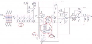
I would really appreciate if the experienced DIYers could help me to understand the function of the following in the attached ckt, pls:
1. How RL201 and associated parallel resistors work
2. P204 & P205 connections to what?
3. R227 and gain head amp gain calculations
I would really appreciate if the experienced DIYers could help me to understand the function of the following in the attached ckt, pls:
1. How RL201 and associated parallel resistors work
2. P204 & P205 connections to what?
3. R227 and gain head amp gain calculations
Attachments
Isn't this a bit above your skills ?I would really appreciate if the experienced DIYers could help me to understand the function of the following in the attached ckt, pls:
1. How RL201 and associated parallel resistors work
2. P204 & P205 connections to what?
3. R227 and gain head amp gain calculations
Anyhow:
3. Gain with relay open is 1+(158/4)/R227 = 40.5 or 32 dB
With Relay closed 1+(158/4 // 47/4)/R227 = 10.06 or 20 dB
1. the relay switches in/out a set of feedback resistors to change the gain
2. P204 is shorted to control the gain relay and P205 would be used for a front panel LED
3. r227 is the feedback resistor. I do not know the gain, would have to calc or simulate
Let me get the point 2 correct, when P204 is shorted, relay coil gets energised and the DPDT switch flips from NC(normally closed) position to NO(normally open) position and the gain is increased for MC(higher) cartridges ? The P204 can be shorted via an ON/OFF switch, right?
Many thanks.
Isn't this a bit above your skills ?
Anyhow:
3. Gain with relay open is 1+(158/4)/R227 = 40.5 or 32 dB
With Relay closed 1+(158/4 // 47/4)/R227 = 10.06 or 20 dB
Indeed I chose an advanced project but I already made some progress and wish to complete the project in a simplified form keeping the headmap.I would like to know:
4. what is the function of R203(100k)?
5. how can I calculate RIAA correction network in the ckt? why this is done in 2 stages? could this be applied in one stage with one OP amp?
6.how does the input attenuation RC network works?
Thanks for your patience.
Forgot the CKT, attached
Attachments
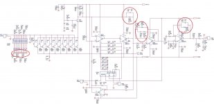
4) R203 sets the feedback loop for the input amp assembly.
5) there are plenty riaa-calculation-tools around. Or make the calculations following the famous lipshitz pape https://pearl-hifi.com/06_Lit_Archive/14_Books_Tech_Papers/Lipschitz_Stanley/Lipshitz_on_RIAA_JAES.pdf
Of course you can do it in one stage, it would be another phono ckt then. Plenty of those around at diyaudio.
6) these are for loading various cartridges. They ideally like to see different inout impedances depending on model. Some believe in input-C as well, i never heard differencies with those values.
I build the HPS 4.1 it is quite complex wouldn‘t recommend it as an early project let alone changing it without knowing what goes on...
Last edited:
- Home
- Source & Line
- Analogue Source
- Hps 5.1