You may want to learn a thing or two from Carlos, diyAudio amp builder speed demon. His regular proto amp build takes literally minutes.I'm going to wait for JPS64's PCB's for stereo. Wiring this amp P2P was a real pain.
One of his artful build in Krill - The little amp that might....
")
Thank YOU, X, we all owe you gratitude for high energy hard work........
Hugh
+1, and thanks to you also Hugh!
You may want to learn a thing or two from Carlos, diyAudio amp builder speed demon. His regular proto amp build takes literally minutes.
One of his artful build in Krill - The little amp that might....
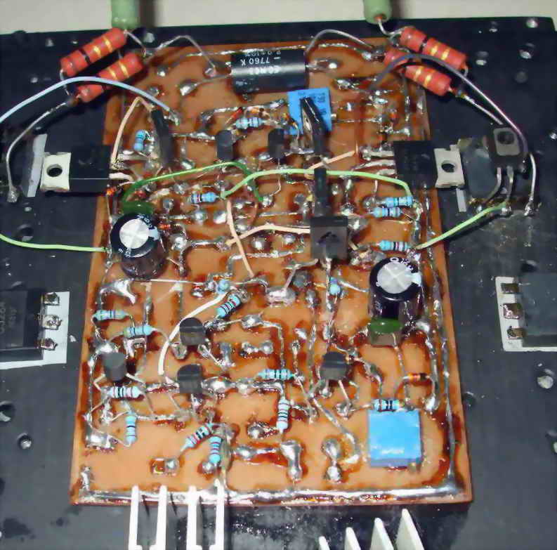
In fact, I did. He suggested use of nail polish to do etch layouts. I use a Sharpie marker. I built the DLH in about 3 hrs from sketch-to-sound. I am going back to this method as it is a lot less error prone than P2P with wire:
I am confused a bit
Usually, on the output, we use larger value caps and on the input, we use 4uF to 10uF film capacitors
Why you use such a high-value capacitor on the input?
Which caps are you referring to? The DLH amp shown a few posts above has some rather large caps on the feedback and bootstrap but is using a 10uF Silmic II vs the 4700uF recommend by the designer. But that’s a different amp and shown here only for purposes of Sharpie based copper etching method.
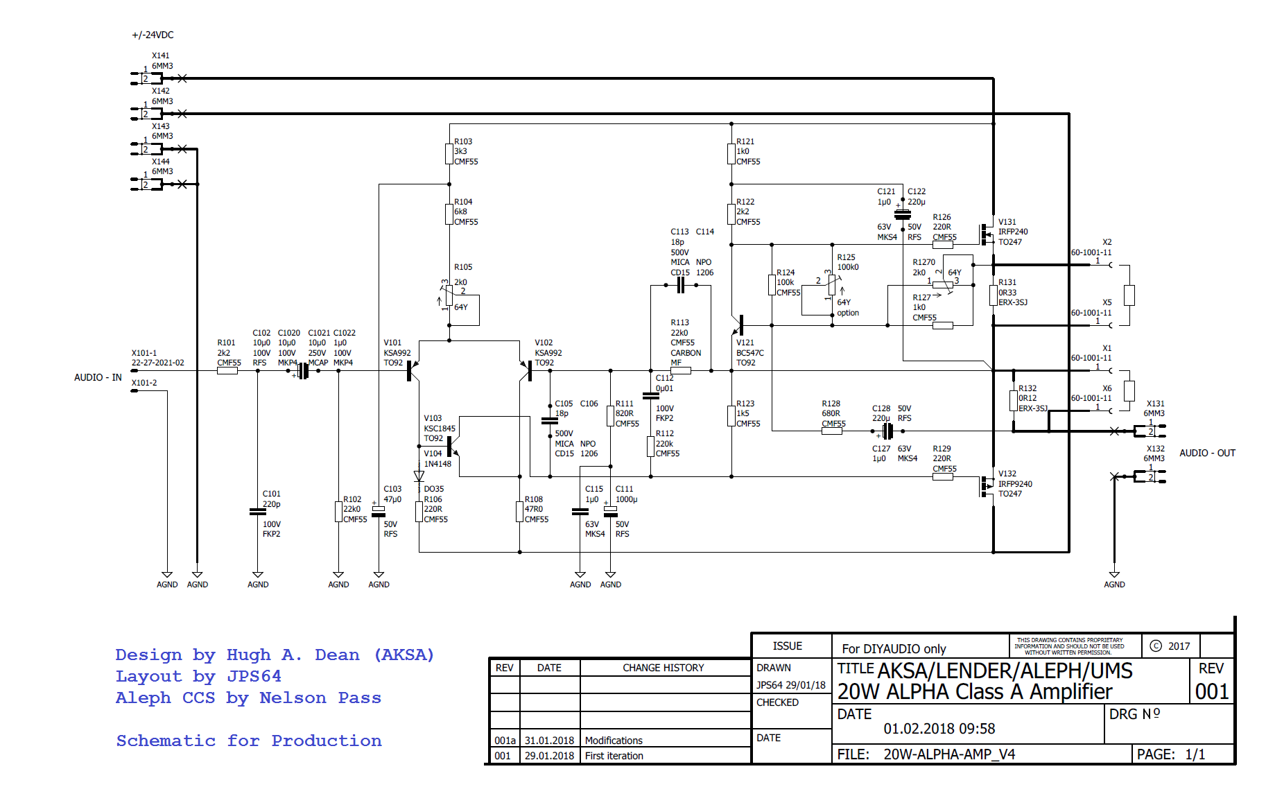
ALPHA 20W Amplifier Design for Production v4
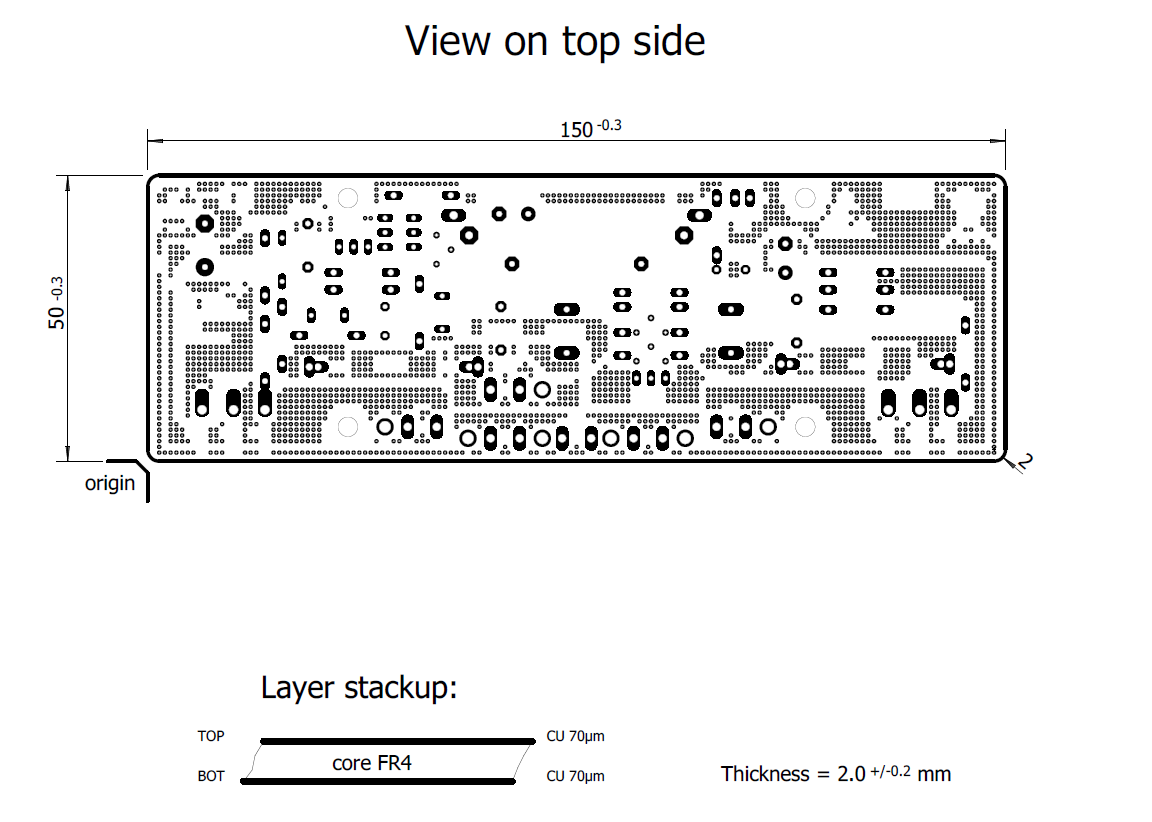
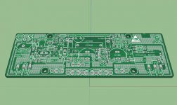
Folks, thanks to JPS64, we have the following for the beautiful pro layout and renders. Looks like it will be a double thickness 70um copper trace board with traces on two sides connected by vias for high current paths for an equivalent 150um thick trace (nice trick there JPS64). The board will be 150mm x 50mm and compliant with UMS heatsink for ease of use.
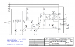
Schematic:
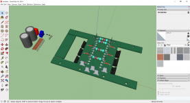
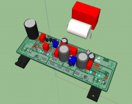
3D Render of built up board:

3D Render of PCB topside:
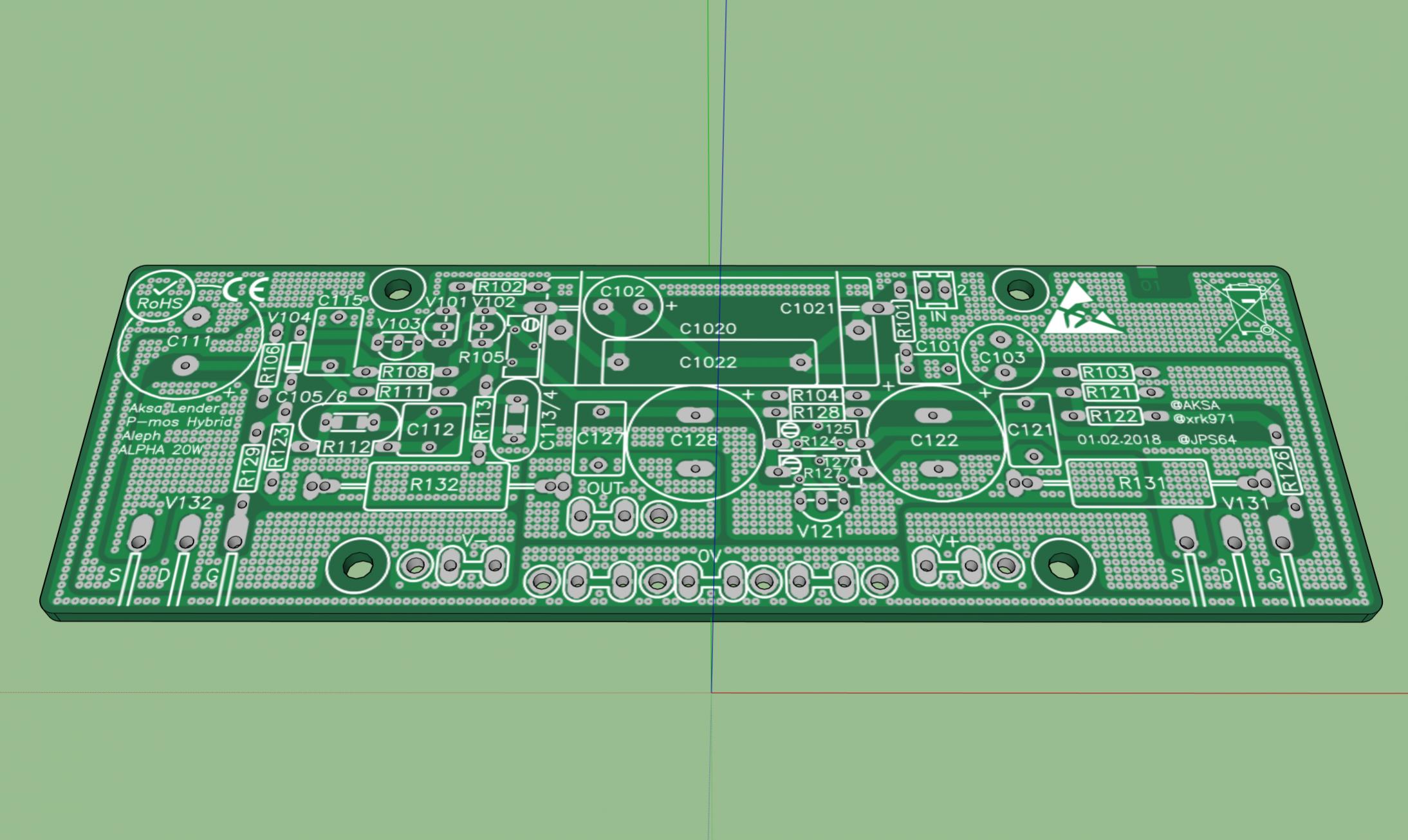
Line drawing of PCB topside components:
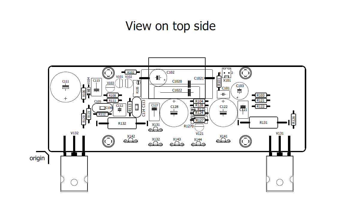
PCB topside vias and stackup showing 2mm thick board with thick traces:
I guess we are ready to start a GB? Let me check with fab houses and I will get back with costs, it's a large double thick copper board so may be a little more than what you may have had in mind. One way to keep costs lower is to go with 35um copper and rely on two sided vias to give us 70um equivalent and use 1.6mm thick boards. What are folks' preferences here?
Folks, thanks to JPS64, we have the following for the beautiful pro layout and renders. Looks like it will be a double thickness 70um copper trace board with traces on two sides connected by vias for high current paths for an equivalent 150um thick trace (nice trick there JPS64). The board will be 150mm x 50mm and compliant with UMS heatsink for ease of use.
Schematic:
3D Render of built up board:
3D Render of PCB topside:
Line drawing of PCB topside components:
PCB topside vias and stackup showing 2mm thick board with thick traces:
I guess we are ready to start a GB? Let me check with fab houses and I will get back with costs, it's a large double thick copper board so may be a little more than what you may have had in mind. One way to keep costs lower is to go with 35um copper and rely on two sided vias to give us 70um equivalent and use 1.6mm thick boards. What are folks' preferences here?
Attachments


Last edited:
Count me in. Thicker board preferred.
Depending on costs, I would want at least 1 pair of boards for the 20w build.
Also, quick question about transformer needs. Is a 400va transformer adequate for a 20w stereo build?
I know there's a way for me to calculate that, but I'm not having terribly much luck finding it.
Thank you Hugh, X and JP for your hard work on what looks like another awesome project!
For class-A amp projects like this the rule of thumb is VA of 6x (or more) the amp's output power in Watts.
20W output x2 = 40 (stereo amp)
40 x 6 = 240VA
I personally wouldn't build the 20W version with anything smaller than a 300VA.
EDIT: Bias is a bit hotter than I realized when I wrote this, see below;
20W output x2 = 40 (stereo amp)
40 x 6 = 240VA
I personally wouldn't build the 20W version with anything smaller than a 300VA.
EDIT: Bias is a bit hotter than I realized when I wrote this, see below;
Last edited:
If you want to run at the full specified 2amp bias, that is P=iV or 2Ax48v = 96W per channel. Stereo is 200W then and at 50% draw of 400VA trafo, there will be significant rail sag to probably +/-20v or 40v total. You could back it off to 1.6A like I did and performance is still quite good, rails will probably be closer to +/-22v at 1.6amps.
One thing that might work really well are those 24v 5amp LED SMPS bricks (with isolated outputs). Series them and you can technically handle 4amps in stereo no problem. I may try that. Otherwise looks like you need a 500VA trafo if you want to get full sag-free power.
One thing that might work really well are those 24v 5amp LED SMPS bricks (with isolated outputs). Series them and you can technically handle 4amps in stereo no problem. I may try that. Otherwise looks like you need a 500VA trafo if you want to get full sag-free power.
For class-A amp projects like this the rule of thumb is VA of 6x (or more) the amp's output power in Watts.
20W output x2 = 40 (stereo amp)
40 x 6 = 240VA
I personally wouldn't build the 20W version with anything smaller than a 300VA.
Nice simple rule, thank you for that 6L6!
Cheers,
Gable
If you want to run at the full specified 2amp bias, that is P=iV or 2Ax48v = 96W per channel. Stereo is 200W then and at 50% draw of 400VA trafo, there will be significant rail sag to probably +/-20v or 40v total. You could back it off to 1.6A like I did and performance is still quite good, rails will probably be closer to +/-22v at 1.6amps.
One thing that might work really well are those 24v 5amp LED SMPS bricks (with isolated outputs). Series them and you can technically handle 4amps in stereo no problem. I may try that. Otherwise looks like you need a 500VA trafo if you want to get full sag-free power.
The price difference between 400-500-600va isn't much, so I'll probably get a 600va.
Antek
4218 @ $51/each:
AS-4218 - 400VA 18V Transformer - AnTek Products Corp
5218 @ $55/each:
AN-5218 - 500VA 18V Transformer - AnTek Products Corp
6218 @ $65/each:
AN-6218 - 600VA 18V Transformer - AnTek Products Corp
Last edited:
- Home
- Amplifiers
- Solid State
- Aksa Lender P-MOS Hybrid Aleph (ALPHA) Amplifier