Any info on my above query!
IRFP150 is about two IRFP240 in parallel. But I don't think you need paralleled output in this low power amp.
I'm not saying that IRFP150 is better but I'm sure most people will prefer the sound of IRFP150 here. It will sound more transparent, rich and high-end or even classy

I will not purchase IRFP150 if I already have IRFP240 though. And there are many better mosfets, but I'm not going to unleash my favorite. But I would prefer the sound of 2SK2648. This one has high Rds and the Vgs will be quite high.
Very important is to put the one with lower Vgs at the bottom (the one with higher trans conductance), and the one with higher Vgs at the top
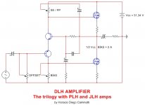
This topology looks like the follow:This very simple design has all the ingredients to satisfy even the most demanding DIYers. The output power in pure class A operation is 15.52 W at 2 ohms and 1 KHz, or 7.76 W at 4 ohms and 1 KHz, or 3.88 W at 8 ohms and 1 KHz. THD is only 0.025 % at 15.52 W and 1 KHz (2 ohms). THD is only 0.0024 % at 7.76 W and 1 KHz (4 ohms). THD is only 0.00091 % at 3.88 W and 1 KHz (8 ohms). Voltage gain = 8,9 dB.
Only two stages. Four transistors. Very few components. Its performance is surprisingly good, despite its total simplicity.
High bandwidth. Ultra low distortion. Input in single ended configuration. Output in single ended or push pull configuration, entirely adjustable by the position of a trimpot. PSRR: 61 dB across the entire audio bandwidth.
I want to hear comments from those who intend to build this simple amplifier.
regards
4QD-TEC: Low distortion Audio amplifier
4QD-TEC: Audio preamplifier circuits (third schematic)
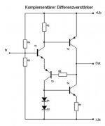
Audio-Vorverstärker | Diskreter Operationsverstärker | Komplementärer Differenzverstärker | Complimentary Long Tailed Pair | Complimentary Difference Amplifier
Vorverstarker mit diskretem OpAmp und komplementarer Differenz-Eingangsstufe - Michael Gaedtke
The showed version is a non inverted amp.
Is it possible to create an inverted amp version ?
Last edited:
Thanks I do not have the equipment or knowledge to simulate it and analyze. I am better off then to look for IRFP150 then rather than use IRFP240.
Hello,
listen to the designer "I think there would be no major drawbacks in using the IRFP240 instead of the first suggested one. I think that there might even be some small advantage due to the lower capacitances involved. It is a matter of simulating it and analyzing what may happen. If something has to be modified, I think it should be very little of the original."
there may be an advantage using the IRFP240... if you have them handy, use them and see...
regards
Prasi
I understood the intention of him but that part "It is a matter of simulating it and analyzing what may happen. If something has to be modified, I think it should be very little of the original." makes me think through to change if required is the question, otherwise I already have the IRFP240 which anyway I am going to use.
thanks a lot for the answers
your DLH has a voltage gain of 8.9dB I would like to decrease it to 3dB by raising the counter reaction.
Will this impact distortion ?
A voltage gain of 3 dB would further reduce the current low total distortion and Jonhson noise. Analyzing at THD levels, the situation could be seen as something between the DLH (with voltage gain) and the DLHSB (without voltage gain).
This topology looks like the follow:
4QD-TEC: Low distortion Audio amplifier
4QD-TEC: Audio preamplifier circuits (third schematic)
Audio-Vorverstärker | Diskreter Operationsverstärker | Komplementärer Differenzverstärker | Complimentary Long Tailed Pair | Complimentary Difference Amplifier
Vorverstarker mit diskretem OpAmp und komplementarer Differenz-Eingangsstufe - Michael Gaedtke
The showed version is a non inverted amp.
Is it possible to create an inverted amp version ?
T4 always acts as a constant current source, differing from the DLH, in which that mode of operation of one of the two transistors of the output stage can be chosen or modified so that both output transistors can operate in push-pull mode.
Pure push pull operation is not possible to achieve in that scheme. The fact that second-order distortion predominates is not unrelated.
Therefore, that scheme only reaches a part of the entire DLH functionality.
The advantage that I see is that it could operate under different voltage levels, something that must be clearly established in the design of the DLH.
The bipolar transistors in the output stage degrade the almost perfect balance management that could be obtained with the pair of complementary input transistors, which does not happen using mosfets.
Attachments
Last edited:
Shipped and shared tracking with all.
It may take 1 or 2 days to appear in their system
Thanks.
Prasi
Could you guys confirm the pcb deliverY?
Is there a BOM for prasi layout? If not I think I will have to look at the layout values printed and order the parts as my boards have almost reached
Regarding the power transformer I have couple of them and need your inputs on which one is suitable.
1. 0-18v 7A*2 dual secondaries toroidal
2. 12-0-12v 3A center tapped EI cores
Or if none of the above suits then I need to order a separate EI or toroidal like 15-0-15v 5A or something which is available locally here.
Thanks for the single rail version DiegoMJ. As the output is cap-coupled, would the input offset pot still be needed? I have indeed built a single rail DLH (as a headphone amp) and it works very well, I skipped the offset pot and put fixed resistors all around for the pots.
I have placed PCB order for this amp for a gentleman and thought of sharing the design through PCBway's website for ease of those that are not familiar with the process.
Anyone can now directly place the order by clicking below link, adding it to cart and checkout.
DLH Amplifier-Trilogy with PLH and JLH Amplifiers- Share Project - PCBWay
I have also added stuffing guide images and schematic to the pcbway webpage. hope this helps.
regards
Prasi
Anyone can now directly place the order by clicking below link, adding it to cart and checkout.
DLH Amplifier-Trilogy with PLH and JLH Amplifiers- Share Project - PCBWay
I have also added stuffing guide images and schematic to the pcbway webpage. hope this helps.
regards
Prasi
I prepared the BOM looking at prasi's published layout/schematic and here is for all reference. Please have a look and let me know if the values are fine. Not sure about the small caps the voltage ratings that we need to consider, as well as the optional components marked with bold '.' on the layout by Prasi. Do we need to use them on the board and does if effect anything?
Thanks
Thanks
Attachments
I prepared the BOM looking at prasi's published layout/schematic and here is for all reference. Please have a look and let me know if the values are fine. Not sure about the small caps the voltage ratings that we need to consider, as well as the optional components marked with bold '.' on the layout by Prasi. Do we need to use them on the board and does if effect anything?
Thanks
Hi manniraj,
here is modified bom for your reference.
I would first build it as it is and add on the optional components to see for any improvement it offers.
regards
Prasi
Attachments
@Prasi, regarding usage of 4.7uf MKP film cap instead of the big 4700uf what voltage rating of 4.7uf should I be looking at!
Also reading the thread here I get that there is no need to look for any matched IRFP240 mosfets are even the transistors BC550/BC560 right.
Thanks
Also reading the thread here I get that there is no need to look for any matched IRFP240 mosfets are even the transistors BC550/BC560 right.
Thanks
- Home
- Amplifiers
- Solid State
- DLH Amplifier: The trilogy with PLH and JLH amps