Hi ejaouen,
I'm not an electronics expert, just a hobbyist, so I can't answer your questions in detail or with authority, but I'll tell you what I do know about these units (from examining the circuit board and using them in practice) and maybe that'll help.
I think this PSU is described as a half-bridge self-oscillating PWM switching supply. The adverts claim more than 90% efficiency. I can't prove that one way or another, but see my comments on performance below.
I'd be surprised if these boards would be technically in the same class as the Connexelectronic ones or even the Abletec ones, but I'd suspect the differences might be much in the protection circuitry as in the actual PSU itself. On the other hand, for price / performance they're hard to beat.
So here's what I know about these boards.
High voltage side
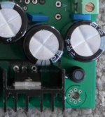
Mains input is followed by a fuse / choke (one side bypassable for 120V operation) / filter capacitors and bridge rectifier arrangement, with two 470uF 200V smoothing capacitors.
Then there's a dropping resistor to power a resin-encapsulated 7-pin mosFET driver module (I don't know what's inside - I think this is the self-oscillating half-bridge PWM driver, possibly based on something like the IRS2153?).
This module drives the two IRF740 moSFETS with their switched outputs feeding a transformer marked 55V (with black felt-tipped pen), with some filter caps across the primary. The board is available in different voltages, and from the traces, I think the transformer would just be swapped to one with different windings to achieve the different secondary voltages.
Low voltage side
The transformer secondary feeds the low voltage side via five diodes. This is presumably two for for the +ve rail, two for the -ve rail, and 1 for the +12v rail, which doesn't share a common ground with the other rails.
The +12V rail has a dropping resistor, feeding a L7812CV regulator with 220uF/25V smoothing capacitors and 0.1uf snubs on the inputs and outputs of the regulator.
The +/- 15V rail has a similar arrangement, with two dropping resistors feeding L7815CV and L7915CV regulators with 220uF/25V smoothing capacitors and 0.1uf snubs on the inputs and outputs of each regulator.
The +/- 55V rail is fed straight from the output of the diodes (i.e. no dropping resistors) into two switchmode power rectifiers (MUR1620CTG/CTR) with 1000uF/63V smoothing capacitors on inputs and outputs of the recitifiers, and also a small choke and snubbing capacitor on the outputs.
Protection?
There is no visible protection circuitry so I think if there is any, then it is fairly rudimentary and probably within the encapsulated mosFET driver, designed to shut down the PWM on over-current or over-voltage detection.
But be warned - when I accidentally shorted one of these (via a shorted L15D board), first it made a fairly strange 'straining' noise, then after a few seconds the fuse shattered and subsequently I found both mosFETS and the driver module were blown. Still thinking about repairing it, but in the meantime I bought another as they're pretty cheap!
Performance
I'm using two of these in my 7-channel home theatre 'baking tray' power amp, based on L15D boards. One supply powers left, centre and rear channels, the other powers right and surround channels. Rear and surround channels are all phase-inverted to avoid any bus pumping. (I also use a separate Velodyne powered sub driven straight off the AV sub output.)
At loud movie-level volumes, using full-range 4-ohm front speakers crossed at 40Hz in a large living room, the supplies barely get warm - in fact the hottest part of the whole setup is the dropping resistors on the L15D boards which can get over 85c!). Similarly, with almost ear-hurting rock music in 'all-channel stereo' (i.e. all channels driven), same thing, the supplies don't even seem to be trying very hard.
I've replaced all buffer capacitors in my L15D boards with 820uF capacitors but this hasn't presented a load problem to the suppliers on power up. There's no 'pop' at startup or shutdown (but I'm using separate speaker protection boards) - the rails seem to power up and down cleanly. Voltages are rock steady and stable. And with amplifier inputs shorted, there's no hiss or hum that I can detect.
So overall they seem to be well suited to audio applications, especially class-D.
Other considerations
The 12V output is useful for a cooling fan - I used a 120cm computer chassis fan and undervolt to around 6V for quietness, but don't try to draw too much current from this rail - it's only 0.5A
The 15V rail (1A) is good for speaker protection boards - mine were designed for AC but I just bypassed the rectifier and fed the 12V regulators directly instead.
Hum. I had problems with hum when taking inputs from my Onkyo AV receiver which I'd modified to provide preamp outputs. Not loud, but annoying and worse on some channels than on others. After trying different grounding layouts, I temporarily disconnected the chassis mains earth and the hum stopped completely. But I don't like dangerous non-earthedd equipment in my living room!
I'd mounted the PSU boards on the chassis using brass standoffs. One of the board's mounting holes is connected to the 0V plane (common ground), so was therefore connected to the chassis (and to mains earth) through the standoff. It was easy to break this trace by scoring it with a sharp object, and once I'd done this (so the circuit ground / 0V is a virtual floating ground and not connected to the chassis / mains earth), I could reconnect the chassis earth and the hum problem was completely gone. I don't know whether this is the best solution, but it worked for me!
In closing, I think they're excellent value for the price. And For hobbyists like me, working to a limited budget where exorbitant shipping costs limit the choices of components, they're an ideal choice for audio applications. Also they're really small for the power they can deliver and they run nice and cool. At the price, it's maybe worth trying one, and upgrading to something more expensive if it doesn't work out - you can always convert it into a bench supply!
Cheers,
Jon
I'm not an electronics expert, just a hobbyist, so I can't answer your questions in detail or with authority, but I'll tell you what I do know about these units (from examining the circuit board and using them in practice) and maybe that'll help.
I think this PSU is described as a half-bridge self-oscillating PWM switching supply. The adverts claim more than 90% efficiency. I can't prove that one way or another, but see my comments on performance below.
I'd be surprised if these boards would be technically in the same class as the Connexelectronic ones or even the Abletec ones, but I'd suspect the differences might be much in the protection circuitry as in the actual PSU itself. On the other hand, for price / performance they're hard to beat.
So here's what I know about these boards.
High voltage side
Mains input is followed by a fuse / choke (one side bypassable for 120V operation) / filter capacitors and bridge rectifier arrangement, with two 470uF 200V smoothing capacitors.
Then there's a dropping resistor to power a resin-encapsulated 7-pin mosFET driver module (I don't know what's inside - I think this is the self-oscillating half-bridge PWM driver, possibly based on something like the IRS2153?).
This module drives the two IRF740 moSFETS with their switched outputs feeding a transformer marked 55V (with black felt-tipped pen), with some filter caps across the primary. The board is available in different voltages, and from the traces, I think the transformer would just be swapped to one with different windings to achieve the different secondary voltages.
Low voltage side
The transformer secondary feeds the low voltage side via five diodes. This is presumably two for for the +ve rail, two for the -ve rail, and 1 for the +12v rail, which doesn't share a common ground with the other rails.
The +12V rail has a dropping resistor, feeding a L7812CV regulator with 220uF/25V smoothing capacitors and 0.1uf snubs on the inputs and outputs of the regulator.
The +/- 15V rail has a similar arrangement, with two dropping resistors feeding L7815CV and L7915CV regulators with 220uF/25V smoothing capacitors and 0.1uf snubs on the inputs and outputs of each regulator.
The +/- 55V rail is fed straight from the output of the diodes (i.e. no dropping resistors) into two switchmode power rectifiers (MUR1620CTG/CTR) with 1000uF/63V smoothing capacitors on inputs and outputs of the recitifiers, and also a small choke and snubbing capacitor on the outputs.
Protection?
There is no visible protection circuitry so I think if there is any, then it is fairly rudimentary and probably within the encapsulated mosFET driver, designed to shut down the PWM on over-current or over-voltage detection.
But be warned - when I accidentally shorted one of these (via a shorted L15D board), first it made a fairly strange 'straining' noise, then after a few seconds the fuse shattered and subsequently I found both mosFETS and the driver module were blown. Still thinking about repairing it, but in the meantime I bought another as they're pretty cheap!
Performance
I'm using two of these in my 7-channel home theatre 'baking tray' power amp, based on L15D boards. One supply powers left, centre and rear channels, the other powers right and surround channels. Rear and surround channels are all phase-inverted to avoid any bus pumping. (I also use a separate Velodyne powered sub driven straight off the AV sub output.)
At loud movie-level volumes, using full-range 4-ohm front speakers crossed at 40Hz in a large living room, the supplies barely get warm - in fact the hottest part of the whole setup is the dropping resistors on the L15D boards which can get over 85c!). Similarly, with almost ear-hurting rock music in 'all-channel stereo' (i.e. all channels driven), same thing, the supplies don't even seem to be trying very hard.
I've replaced all buffer capacitors in my L15D boards with 820uF capacitors but this hasn't presented a load problem to the suppliers on power up. There's no 'pop' at startup or shutdown (but I'm using separate speaker protection boards) - the rails seem to power up and down cleanly. Voltages are rock steady and stable. And with amplifier inputs shorted, there's no hiss or hum that I can detect.
So overall they seem to be well suited to audio applications, especially class-D.
Other considerations
The 12V output is useful for a cooling fan - I used a 120cm computer chassis fan and undervolt to around 6V for quietness, but don't try to draw too much current from this rail - it's only 0.5A
The 15V rail (1A) is good for speaker protection boards - mine were designed for AC but I just bypassed the rectifier and fed the 12V regulators directly instead.
Hum. I had problems with hum when taking inputs from my Onkyo AV receiver which I'd modified to provide preamp outputs. Not loud, but annoying and worse on some channels than on others. After trying different grounding layouts, I temporarily disconnected the chassis mains earth and the hum stopped completely. But I don't like dangerous non-earthedd equipment in my living room!
I'd mounted the PSU boards on the chassis using brass standoffs. One of the board's mounting holes is connected to the 0V plane (common ground), so was therefore connected to the chassis (and to mains earth) through the standoff. It was easy to break this trace by scoring it with a sharp object, and once I'd done this (so the circuit ground / 0V is a virtual floating ground and not connected to the chassis / mains earth), I could reconnect the chassis earth and the hum problem was completely gone. I don't know whether this is the best solution, but it worked for me!
In closing, I think they're excellent value for the price. And For hobbyists like me, working to a limited budget where exorbitant shipping costs limit the choices of components, they're an ideal choice for audio applications. Also they're really small for the power they can deliver and they run nice and cool. At the price, it's maybe worth trying one, and upgrading to something more expensive if it doesn't work out - you can always convert it into a bench supply!
Cheers,
Jon
Straining noise sounds like hard core saturation. Inductance drops to nearly zero then and the FETs running into a short. This normally destroys the primary switching side completely.  I've had experience with this from a modified ATX supply running at hard (non working) current limit. In the end there was no fuse anymore and the FET legs were molded together.
I've had experience with this from a modified ATX supply running at hard (non working) current limit. In the end there was no fuse anymore and the FET legs were molded together.I really like the sound of my 4 x Sanwu 3118 mono boards, for movies and television. Problem is. They bi-amp 2 B&W speakers that are rated at 200W each in 8 ohms. This is not enough for music, to my ears. These speakers sound brilliant, loud and dominating, on a big AB amplifier but I want to run Class D.
Have been looking at Icepower, but they are pretty unobtainable and when there actually are some on ebay, the price is there after.
I have read all 39 pages in this thread, and have found some interesting stuff.
Is the Abletec the way to go? I have to pay a bit more for shipping, than for the actual PSU. So I really want to be sure.
ABLETEC ALPO400-5301-D, 900 Watt Peak, OUT: +53V, -53V, +7.5V, +5.6V DC, | eBay
Also.
Does these IRS2092 have the same counterfeit problems as TI chips? These cheap IRS2092 boards all look the same... Any recommended sellers?
IRS2092 CLASS D Audio Power Amplifier AMP Kit 200W MONO Assembled Board Hot | eBay
I know I'm never going to play these speakers at their power rating, but I still want to be able to deliver 4 x 100W in 8R. This means 4 x IRS2092 boards. So this would need an 800W SMPS?
With 8-ohm speakers, the efficiency of class-D amps are typically around 90%, so you should only need a 450W-500W SMPS like this one:
http://www.ebay.co.uk/itm/High-Qual...tching-Power-Supply-Transformer-/162167259142
Last edited:
I agree with the previous post that with the efficiency of Class D amps, unless you were going to drive all four amps continuously at full power with with sine wave inputs, you're unlikely to need as much as 800W. But better safe than sorry I always say, if you can afford the extra power, go for it!.
There's been good feedback about the Abletec supplies in this and other threads, so you probably won't go far wrong with that as a choice. I believe you have to put a load across the lower voltage outputs to make it work properly - best to read up on this in the forums. As I've mentioned previously though, , I'm using two of the much cheaper (because of free shipping form China) 500W +/-55V units like these or these very successfully to power 7 x IRS2092 L15D boards - they work fine but it's just they don't have the greatest protection against shorts.
I don't think its so much that they're counterfeit chips, more that there are good and not-so-good implementations of the IRS2092 reference design, and the quality of the other components on the boards can vary. My personal choice would be LJM's design as these have had great feedback from people who've used them, and they use high quality components; also LJM is a regular contributor to these forums and has provided much useful information about these amps. I bought mine as stereo kits from here (i.e. two boards - I bought as kits because I like soldering and I've found poor joints on assembled boards in the past!), but they are also available assembled, and there are are other sellers to on Ali and on eBay. Others have recommended Connexelectronics as a supplier of well designed high quality boards.
There's a wealth of information about the IRS2092 in the IRAUDAMP7S reference design document and in particular, when using multiple IRS2092 boards there are two things to consider. Firstly, if using them on the same power supply, you should use op-amp phase inverters (schematic on P32) and reverse the speaker connections on alternate channels to avoid 'bus pumping' (described on P26), especially if there's a lot of bass. Secondly, the switching frequencies should either be set very accurately, or separated by at least 25KHz to avoid potential audible inter-channel interference (P22). While the LJM board doesn't have adjustable switching frequency, it's a simple matter to replace R11 (270 ohm) with a multi-turn 500 ohm trimpot.
ANyway, hope this helps, and good luck with your project!
Is the Abletec the way to go? I have to pay a bit more for shipping, than for the actual PSU. So I really want to be sure.
ABLETEC ALPO400-5301-D, 900 Watt Peak, OUT: +53V, -53V, +7.5V, +5.6V DC, | eBay
There's been good feedback about the Abletec supplies in this and other threads, so you probably won't go far wrong with that as a choice. I believe you have to put a load across the lower voltage outputs to make it work properly - best to read up on this in the forums. As I've mentioned previously though, , I'm using two of the much cheaper (because of free shipping form China) 500W +/-55V units like these or these very successfully to power 7 x IRS2092 L15D boards - they work fine but it's just they don't have the greatest protection against shorts.
Does these IRS2092 have the same counterfeit problems as TI chips? These cheap IRS2092 boards all look the same... Any recommended sellers?
IRS2092 CLASS D Audio Power Amplifier AMP Kit 200W MONO Assembled Board Hot | eBay
I don't think its so much that they're counterfeit chips, more that there are good and not-so-good implementations of the IRS2092 reference design, and the quality of the other components on the boards can vary. My personal choice would be LJM's design as these have had great feedback from people who've used them, and they use high quality components; also LJM is a regular contributor to these forums and has provided much useful information about these amps. I bought mine as stereo kits from here (i.e. two boards - I bought as kits because I like soldering and I've found poor joints on assembled boards in the past!), but they are also available assembled, and there are are other sellers to on Ali and on eBay. Others have recommended Connexelectronics as a supplier of well designed high quality boards.
There's a wealth of information about the IRS2092 in the IRAUDAMP7S reference design document and in particular, when using multiple IRS2092 boards there are two things to consider. Firstly, if using them on the same power supply, you should use op-amp phase inverters (schematic on P32) and reverse the speaker connections on alternate channels to avoid 'bus pumping' (described on P26), especially if there's a lot of bass. Secondly, the switching frequencies should either be set very accurately, or separated by at least 25KHz to avoid potential audible inter-channel interference (P22). While the LJM board doesn't have adjustable switching frequency, it's a simple matter to replace R11 (270 ohm) with a multi-turn 500 ohm trimpot.
ANyway, hope this helps, and good luck with your project!
Very informative post! Thank you. I have been looking at the L15DSMD from LJM and I think I will be going with 4 of those. The price difference is not much. Thanks for the links. Im also eligble for free postage, so I will be going with the China smps.
I wish I knew how to calculate the current needed from a 50V smps.
I wish I knew how to calculate the current needed from a 50V smps.
I have been looking at the L15DSMD from LJM and I think I will be going with 4 of those.
Or you could look at the L15D Pro, which I think have built-in speaker protection - I would certainly recommend DC protection circuits for your speakers, whether on-board or separate. I did buy one L15DSMD pre-assembled and it was fine although after tightening the power and speaker connections a couple of times I had to re-solder them to the board, as a couple of the joints were 'dry' and had cracked. Gain seemed a little higher than the standard L15D boards, not sure why.
As for your question on current, the reference design says that at +/-50V the L15D delivers 125W into 8 Ohms, and at 120W it's said to be 90% efficient. So that should mean it consumes around 140 Watts fully driven. With a supply rail difference of 100V (+/-50V), I think that would mean each board would draw around 1.4 amps. And if my maths and assumptions are correct, four boards fully driven would need around 560 Watts. In which case a 500W supply should be adequate, since it's unlikely you would ever drive all four boards simultaneously at maximum power. If I've got this wrong, hopefully someone more knowledgeable can correct me!
But I'm driving four boards off one 500W supply (and three off a second one), without any problems at all. At one stage while waiting for my second supply to arrive, I was driving all seven boards off one 500W supply and didn't have any problems with that setup either, but felt that it was probably underpowered if I even pushed it to its limits!
Thanks for the PSU link with free shipping. Ordered now. Still deciding amp board. I have read that the L15 board soubs nicer than the board that sparked this thread. So thats what Im getting. About the L15D P thats the one running on AC with an onboard rectifier? I wont be needing that?
Speaker and power connections will only be tightened omce. Im building a stationary amp.
Should I not be able to change gain myself? Im using a DAC that also acts like a preamplifier, so I lowered gain alot on my Sanwu boards.
Speaker and power connections will only be tightened omce. Im building a stationary amp.
Should I not be able to change gain myself? Im using a DAC that also acts like a preamplifier, so I lowered gain alot on my Sanwu boards.
So this one
Assembled LJM L15D-Pro Stero Power Amplifier Board IRS2092 IRFB4019 J163 | eBay
has built in speaker protection. Does that also eliminate turn on and off pop?
What if I buy the cheaper boards and do not use speaker protection?
Assembled LJM L15D-Pro Stero Power Amplifier Board IRS2092 IRFB4019 J163 | eBay
has built in speaker protection. Does that also eliminate turn on and off pop?
What if I buy the cheaper boards and do not use speaker protection?
Absolutely. I only mentioned this because I originally used one L15D-SMD alongside standard L15D boards and found that it was louder for the same input level. Only relevant if you mix boards.Should I not be able to change gain myself? Im using a DAC that also acts like a preamplifier, so I lowered gain alot on my Sanwu boards.
Yes, but more importantly, it protects your speakers against damaging DC voltages should the amp fail for any reason.So this one
Assembled LJM L15D-Pro Stero Power Amplifier Board IRS2092 IRFB4019 J163 | eBay
has built in speaker protection. Does that also eliminate turn on and off pop?
Then, if the amp fails (e.g. output short or component failure), your speakers could receive the full DC +/- supply voltage, which will most likely destroy them. The protection circuits are designed to detect a DC voltage across the speaker outputs and will open (or not close) the relays if present. They also usually have a delayed start (muting) to avoid 'thump'.What if I buy the cheaper boards and do not use speaker protection?
I don't know whether separate protection modules are better than the on-board circuits. I decided to use separate modules mainly for size and cost considerations. Also because I read that if protection was triggered and opened the relay at high power, the relay contacts could be destroyed by arcing, and it's much easier to replace a protection module / relay than a L15D board / relay in my setup. There's quite a good article on speaker protection circuit characteristics here.
By the way, I've put photos of the build of my Baking Tray 7-channel amplifier in the gallery at Baking Tray Amplifier - My Photo Gallery, with a build log in the photo descriptions. There are some possibly useful tips there including my schematics, prototype board layouts and connections for phase inverters, how I implemented remote control power on/off, pretty front panel indicators using TOSlink cables, and some information on L15D switching frequency adjustments. Hope this is helpful.
Okay. I have no speaker protection circuit in my Sanwu amplifier. Will surely add that to this build. Also. The TI chips have mute function. IRS doesn't so I will need that relay to get around the "on/off thump" problem.
This is somewhat off-topic, and at the same time not. Alot of the speaker protection boards have 2 relays and combined GND/-. This is probably basic speaker knowledge, but is it a good idea connection the output - from 2 x IRS2092 boards? Or do I need to buy the more expensive mono speaker protectors. Because then it's alot cheaper just choosing L15D-Pro boards.
Also. NICE build log. Love how compact you made it!
Last edited:
I don't think it matters because the ground is common at the power supply anyway. I used the 2-channel boards for cost & space reasons.This is somewhat off-topic, and at the same time not. Alot of the speaker protection boards have 2 relays and combined GND/-. This is probably basic speaker knowledge, but is it a good idea connection the output - from 2 x IRS2092 boards? Or do I need to buy the more expensive mono speaker protectors. Because then it's alot cheaper just choosing L15D-Pro boards
Two things to watch out for though. First, if you're using phase inverters, reverse the speaker connections AFTER the protection boards (and don't ground the speaker terminals themselves), otherwise there's a risk of shorting; and check for output shorts before powering on. Obvious really, but I forgot, and found this out the hard and expensive way.
Secondly, in multi-channel setups, there's a potential for hum from ground loops both internally and with external equipment. I had slight hum but only when my Onkyo AVR was connected; I eliminated this by breaking the connection between the amp's ground and the chassis earth, i.e. making the amplifier's ground plane a 'floating' ground. With the PSUs I used, this can be done by breaking the small trace between the ground plane and the screw hole (pictured) with a sharp object, or using insulated standoffs.
And I didn't use a separate 12V AC supply either, I just used the 0V/+15V DC rail from the PSU, and removed & bypassed the rectifier on the protection boards so the supply went directly to the 12V voltage regulator. Works a treat.
Attachments
As per your suggestion I'm going with separate speaker protection circuit. I have read that the L15D(non-pro) without speaker protection, has less distortion, probably because of component placement. (Closer to each other etc.)
Found these bad boys. UPC1237 Dual Channel Speaker Protection Circuit Board Boot Mute Delay DC 12V-24V | eBay
They will run 12VDC natively? Do you think I can trust that?
If so, I finally got all the components together. Will order the L15D boards tonight.
Found these bad boys. UPC1237 Dual Channel Speaker Protection Circuit Board Boot Mute Delay DC 12V-24V | eBay
They will run 12VDC natively? Do you think I can trust that?
If so, I finally got all the components together. Will order the L15D boards tonight.
As per your suggestion I'm going with separate speaker protection circuit. I have read that the L15D(non-pro) without speaker protection, has less distortion, probably because of component placement. (Closer to each other etc.)
Found these bad boys. UPC1237 Dual Channel Speaker Protection Circuit Board Boot Mute Delay DC 12V-24V | eBay
They will run 12VDC natively? Do you think I can trust that?
If so, I finally got all the components together. Will order the L15D boards tonight.
I think those should be OK - but if you're using the same PSU I am, you might need to run them off 0/+15V rail rather than the 12V rail - it's only 0.5A and I found my boards just didn't work reliably off that rail. On testing, the protection circuit would trigger, but rather slowly if I reversed the speaker DC polarity. At 0/+15V they triggered pretty much instantly.
You can test the boards easily (and I think it's a good idea to do so!) by just connecting power and then putting a DC voltage across their inputs (suggest not connected to the L15D boards when you do this) - I just used a 1.5V or 9V battery.
Now I ordered 1 PSU. 4 x L15DSMD and 2 protection boards. I figured out that amp GND and the - on ouput terminal are the same. It's visible on the PCB tracing.
I ordered the PSU you suggested. Description says that the 15V line has shared GND with the 55V. Could this not produce some noise issues? The 12V line has it's own GND apparently.
Don't think it's a problem - the L15D has a common ground (for spkr GND and power GND) and this is probably the same for the protection boards too (it is for mine), so one common ground right the way through. If so, I'd think that introducing another ground (i.e. the 12V GND) and connecting it (via the protection and L15D boards common ground) to the 55V and 15V GND is likely to introduce more problems at the PSU end - there's probably a good reason they're separated there. Thinking about it, maybe that's why my protection boards didn't work so well when I connected them to the 12V rail!
If you don't care about looks they have some decent options!
Server Cases, Rackmount Server Chassis - Newegg.com
Server Cases, Rackmount Server Chassis - Newegg.com
If you are like me, you have probably been looking for a price-appropriate but nice looking and functional case to put these budget amplifiers and their budget power supplies in.
I can't handle spending $300 on an all aluminum heat finned rack mount case for class AB type amps. But that's about all I can find when looking for something big enough to hold two of these amps and an Abletec power supply.
I don't mind thin steel cases and even better if they have nice aluminum panel fronts. Here are some low cost options. Industrial 3U server rack mount cases. Cheap compared to the audiophile grade stuff they sell - and pretty good looking functional too.
Here's a $50 (shipping included) 3U case:
iStarUSA D-313SE-MATX Black Aluminum / Steel 3U Rackmount Compact Industrial Chassis - Black Bezel 2 External 5.25" Drive Bays - Newegg.com
It just needs a small filler panel on back. If you have an old mini ATX power supply you can use the rear panel from that to get a power switch and IEC power jack.
- Home
- Amplifiers
- Class D
- 200W IRS2092 Amp for $20