Dear all, please could someone explain to me in the simplest of terms how to wire from the two rca inputs to a 6SN7 valve base and then to a 6 pin potentiometer, I am a complete novice so I would really appreciate the most detailed but simplified explanation or even a photograph or diagram, thanks for your time and answers in advance.
Ian
Ian
It would scare me as well 
Its very important that you add a bleed resistor from the output to ground. If nothing is connected to the output, then the output cap has no means to charge... and you don't want it to charge via the headphones as you plug them in. If the headphones are permanently connected then there isn't such a problem, but its good design to look at all aspects that can arise.
A 1k would take the output to zero volts in around 10 seconds assuming the cathode was at say 50 volts.
Have you figured the wiring of the pot out now ?
Thanks I will do that, does it have to be 1k as they are a bit big, still no luck with the wiring of the pot I'm afraid, I don't know if the rca inputs are supposed to actually go to the valve pins or directly to the pot, I have a 6 pin pot and the wire is currently 2 core and screen, one piece from valve pins 1 and 4 of the 6NS7 and one from the rca inputs, does each wire go to its own pin on the pot or do they go together, what I am saying is are all pins used on the pot or just the 3 near to the chassis.
Thank you Ian
Thank you Ian
I assuming the audio output is only going to be a few volts at most, which if so means a 1 watt resistor would be fine.
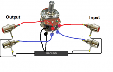
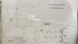
Your circuit shows the grid of the valve wired directly to the wiper of the pot. That's the middle terminal of the three, the one I called 'output' in the diagram above.
The ground terminal of the pot is as shown in my earlier diagram and so you need a wire from there to ground in the amp.
The input side of the pot goes to the middle pin of the input RCA socket and the outer 'ground' part of the socket connects to ground in the amplifier. The same ground point you used for the pot.
I don't know which pin the grid is without looking it up (lol, I don't do valves)
Your circuit shows the grid of the valve wired directly to the wiper of the pot. That's the middle terminal of the three, the one I called 'output' in the diagram above.
The ground terminal of the pot is as shown in my earlier diagram and so you need a wire from there to ground in the amp.
The input side of the pot goes to the middle pin of the input RCA socket and the outer 'ground' part of the socket connects to ground in the amplifier. The same ground point you used for the pot.
I don't know which pin the grid is without looking it up (lol, I don't do valves
)Do you just plug on the main voltage when the hole amp is assembled at hope it all works and everything is assembled correct?
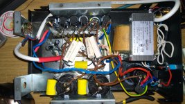
I like to test the PSU's "slowly" before I dare just to turn it on with "full" main voltage. I normall use a vario trafo and measure the current to check if something is completely wrong. It is nice to check that positive DC voltage is at the + of the capasitors with just maybe 10V of main and then slowly apply the main voltage. But maybe that is just me........
I like to test the PSU's "slowly" before I dare just to turn it on with "full" main voltage. I normall use a vario trafo and measure the current to check if something is completely wrong. It is nice to check that positive DC voltage is at the + of the capasitors with just maybe 10V of main and then slowly apply the main voltage. But maybe that is just me........
I guess you could use a low wattage bulb tester and check the HT but you would have to remove the valve first (filament current would draw to much on a bulb).
Which brings another point. I don't see any bleed resistors on the HT lines. A 220k would be a good safety feature and would bring the HT down to safe levels after around 60 secs.
Any resistor MUST be rated for the high voltage as well as the expected power dissipation.
Which brings another point. I don't see any bleed resistors on the HT lines. A 220k would be a good safety feature and would bring the HT down to safe levels after around 60 secs.
Any resistor MUST be rated for the high voltage as well as the expected power dissipation.
Thanks Mooly, by the HT lines do you mean the 6.3v winding, don't suppose you live near London do you.
HT = HV = B+ = high tension = high voltage
There are resistors from the valve pins 1 and 4 of both tube bases, this is the grid and I presume the HT line
NO, you must connect the HT to the anode of each triode.
Thanks Mooly, by the HT lines do you mean the 6.3v winding, don't suppose you live near London do you.
Not exactly
and no, nowhere near London.A low wattage mains filament bulb in series with the primary winding will limit current in the event of a fault, however it would not support the heater current of the valve.
So simplest method is to just leave the valve/s out and power up with the bulb whilst checking the high voltages come up to the expected values. They will be a little high with no load, that's normal.
And remember to discharge the rails safely with an appropriate resistor. Those caps will retain their charge for days.
Does anyone happen to know which side of the 6sn7 is which ie is the left channel 1 to 3 and right channel 4 to 6, thanks again.
Ian
Really...? I hate to say it, but this question implies a level of understanding that suggests to me that it would be unwise to continue with this project. It's an OTL project connecting to headphones - you could potentially get something wrong in the wiring and you won't live long enough to listen to it.
The reality is that it both sides are the same in the valve, so which side carries which signal solely depends which side has been wired to which input and to which output. There is no special significance to left and right - both channels should be electrically the same.
- Status
- This old topic is closed. If you want to reopen this topic, contact a moderator using the "Report Post" button.
- Home
- Amplifiers
- Tubes / Valves
- OTL tube headphone amp