When very high power is not required, would tap3255 be better with 19v 90w laptop Power supply , or it's better to go for tpa3251 or tpa3250 with same power supply.. evm boards are available for all of them at same cost ..
Probably the 3251 over the 3255, as it looks like they change up the latter's output transistors and thus compensation/loop to handle the bigger power capacity. The 3251 has slightly lower gain and lower distortion, especially at low power.
Okay, to shorten that.. the IRS2092 amps usually benefit from higher supply voltages.
Thank you.
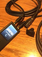
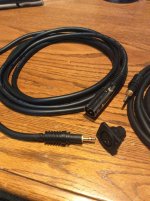
To utilize the balanced capabilities of the 3255EVM and a Pono player, I bought some Monoprice XLR cables and replaced the female connectors with TRS plugs. When I put the board in a case, I want to avoid the RCA connectors.
The Monoprice XLR cable appears to be well constructed and yet is quite flexible. I can't test it until I put the board in a case, which has been ordered, but has not yet arrived.
The Monoprice XLR cable appears to be well constructed and yet is quite flexible. I can't test it until I put the board in a case, which has been ordered, but has not yet arrived.
Attachments
-
 D1953120-F3A5-4307-B075-7123FF1D91D0.jpeg.f470893f143c2966ed92dcb73ef5d7fe.jpeg843.3 KB · Views: 445
 -
 DD3C6E9A-E7F4-4D74-B777-4B1D193093E5.jpeg.844671d43b78046abcaa25c5f9ea8380.jpeg899.8 KB · Views: 430
 -
 E67A7DC6-F186-424A-9247-C528D3C27019.jpeg.d6e8491133270896ecefeb16c2c33d54.jpeg772.8 KB · Views: 427
If a passive volume control is to be added to this circuit, what would be the best value for the potentiometer?
Ideally about a tenth of the input impedance
 which is impossible.
Or at least not less than the input impedance, and that gives an effective 5k impedance. Even that will be a nightmare for most audio sources.
Best is a active preamplifier stage, It seems to new electronics built around MUSES 8820 popping up on Ebay and Aliexpress. Will look in to that myself.
Last edited:
Something like the Kuartlotron buffer has 47 Ohms output impedance, and one can change it for 4.7 if wanted. So would'nt a simple unity gain buffer also give freedom with regards to the potentiometer?Ideally about a tenth of the input impedance
I have a DAC with balanced ouputs, via 3-pin XLR connectors, but I'm having some difficulty wrapping my head around the XLR to dual RCA wiring scheme needed to implement the connection. I'm aware of the 3-pin molex connection that is also available, but it's the 3 into 4 for the RCA connectors that is hurting my brain.
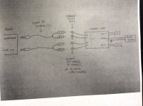
I have the same issue, especially after the Pono technical bulletin emphatically warned against using RCA terminals under any circumstances. Fortunately, gmarsh, the designer/builder of the excellent “Wiener” TPA3118 board, sent me the attached schematic.
I must keep reminding myself that the tip of one Pono TRS plug is the +, while the ring is the - of one channel of the balanced outputs. The sleeve is connected to the shield. Two shielded cables with RCA connectors are needed to connect the + with the center pin of one RCA and the - the center pin of the other RCA. That takes care of one channel. Duplicate all that for the second channel.
The three prong Molex connectors (one for each channel) are used to the bypass the RCA connectors. The center prong is the shield, another prong the +, and the remaining prong the -. Before converting from RCA to Molex, which leads are then connected to female XLR panel connectors, I used a DVM to confirm, by continuity, which of the prongs was connected to the center connector of which RCA terminal.
I think what is confusing to me is the need to step away from the typical SE connection of L, R, ground to achieve two discrete channels, to embrace the DIFF requirement of discrete + and - connections for each channel, in addition to the separate shield connection, as illustrated by gmarsh’s diagram. Does any of this make sense?
Attachments
Last edited:
Does any of this make sense?
Not really.
But thanks.The diagram unfortunately shows a single line connecting the TRS connector to two RCAs, but the written description suggests three connections (+, -, and shield) for each channel. There are better graphical representations available, from Jensen among others, and I have seen them, but have not implemented them.
Not to worry, however. Mike (mboxler) sent me a couple of molex fan connectors with wiring, and I've wired them to Neutrik female xlr panel connectors situated close to the amp. I'm using standard (Monoprice, in fact) xlr cabling from the DAC (with dual ESS 9018 chips in differential mode) to the amp. No RCAs in the picture.
Veils have been lifted, as they say.
If a passive volume control is to be added to this circuit, what would be the best value for the potentiometer?
I found this thread interesting.
Simplest Passive Preamp design
Mike
Yes, of course that will work,and seems to be a splendid choice. Another solution is a buffer built around a LME49600. Either way, still needs a max 10k log potentiometer.Something like the Kuartlotron buffer has 47 Ohms output impedance, and one can change it for 4.7 if wanted. So would'nt a simple unity gain buffer also give freedom with regards to the potentiometer?
And it depends on the ability and willingness to build electronic circuits from scratch.
If a passive volume control is to be added to this circuit, what would be the best value for the potentiometer?
There is no cut and dry answer. I use a simple 20k smt 24 step pot. Rhing uses 15k input transformers which should be a poor fit but sounds great. There is no simple answer.
One basic/novice question regarding amp power .. if for example if we say amp output 175w with 10% distortion and 1w with 0.006% distortion.. what decides the output power of the amp ? Is it power supply of the amp or gain settings of the amp or the input signal level after volume control ??
All of the above, and then some
First, Ohm's law is your friend. Since you didn't specify the speaker load, let's assume 8 ohm.
Watts = volts squared / resistance; therefore, 175 = 37.4 volts squared / 8.
Remember, 37.4 volts RMS = 105.75 volts peak-to-peak.
Watts = volts * current; therefore, 175 = 37.4 volts * 4.7 amps.
These amps use single voltage power supplies, so, you need a 105.75 volt power supply that's capable of supplying 9.4 amps of current to drive two 8 ohm speakers at 175 watts.
As you approach these limits, distortion starts to kick in.
However, these amps can take a maximum 53.5 volts. In order to get 175 watts, you would need to drive the speakers BTL (bridge tied load). What this means is that the + side of the speaker will get 53.5 volts peak-to-peak, and the - side of the speaker will get 53.5 volts peak-to-peak (180 degrees out of phase). And since the voltages are 180 degrees apart, there can be a total of 107 volts peak-to-peak across the 8 ohm driver, or 37.8 volts RMS.
Ohm's law...Watts = volts squared / resistance. 37.8 squared / 8 = 178.6 watts.
I sure hope that answers your question (and that I got the math right).
Mike
There is no cut and dry answer. I use a simple 20k smt 24 step pot. Rhing uses 15k input transformers which should be a poor fit but sounds great. There is no simple answer.
I like the use of the Altec Peerless 15335A input transformers to convert from unbalanced RCA inputs to the differential/balanced inputs of the TPA3255EVM amp, but I'm finding with extensive listening that I like using the unbalanced RCA inputs on the board more. The sound is more forward, lively and engaging, and this seems to pair well with my ARC tube phono stage and tube line stage preamps.
If anyone needs good interconnects to use with their TPA3255 amp, I recommend following this recipe for DIY cables using Belden 8402 microphone cable and Switchcraft 3502AAU RCA phono connectors:
The Vintage Beat: A Forgotten Voice from the American Recording Studio – Jeff's Place
Thanks a lot folks for your suggestions on how to put in a volume control. It has given me a lot of leads to work on. Will implement what I can, then let you know the results.
Another option is Sure Electronics PGA2311 volume control board. It says " output impedance was as low as 1k ohm." so I thought I might give that one a try. When I get it, I'll let you know.
Sure Electronics' webstore Digitally Controlled Stereo Electronic Audio Volume Control Board VC05 - PGA2311
- Home
- Amplifiers
- Class D
- TI TPA3255EVM