Hello All,
I’ve recently picked up a pair of Tamura F-925 PP output transformers (5K, 30W, 200mA, UL taps) to build a stereo amplifier. I’ve built a number of guitar amps before but only one stereo amp (6V6GT PP UL, simple but sounds good). Since the Tamuras should be nice transformers, I’d like to have a correspondingly nice circuit to let them shine.
All the usage information I’ve seen on these transformers are in Japanese, which I will link to for reference as the schematics are understandable:
I would like approx 30W per channel output, and will build as a stereo amplifier with one power transformer. I have a set of Shuguang EL34 output tubes to be used, as well as one pair of Svetlana KT88s (which I can try to decide if I prefer the sound to EL34). Would like to use noval socket preamp tubes, hoping to keep it to a total of three preamp tubes for both channels. I have access to all of the 12A_7 family, ECC88, 12BH7, 6AN8, among other common and not-so-common noval preamp tubes.
I’m willing to use solid state components where preferred (e.g. regulated voltage, bias servo, MOSFET CCS, etc). Would like to keep the signal path itself all-tube, if only to be able to say it’s an “all-tube amplifier”. But that requirement is not firm, if it turns out that, say, MOSFET drivers make a better design fitting with the preamp tube limitations.
Thinking B+ should be around 430-440V with fixed bias.
I would appreciate any suggestions on the amplifier topology, including UL vs triode (is it worth having this function switchable or better to design around one more of operation only?), output tube choice, preamp tube choice, phase-inverter design, gain stage(s), driver stage(s), global NFB, and which, if any, of the frequently recommended DIY Audio designs would be a good starting point. And I do realize that this amplifier will require a lot of work on my part, both in the design and construction.
Thank you for any help.
I’ve recently picked up a pair of Tamura F-925 PP output transformers (5K, 30W, 200mA, UL taps) to build a stereo amplifier. I’ve built a number of guitar amps before but only one stereo amp (6V6GT PP UL, simple but sounds good). Since the Tamuras should be nice transformers, I’d like to have a correspondingly nice circuit to let them shine.
All the usage information I’ve seen on these transformers are in Japanese, which I will link to for reference as the schematics are understandable:
- A KT88 UL amplifier with 37W output: http://www.tamura-ss.co.jp/tsbar/pdf/trance.pdf (pdf, scroll to page 10 for the T-X88P amplifier)
- A KT120 UL amplifier with approx 45W output: http://www.ktamp.com/hk25_info.html (schematic linked on page at ■HK-25・回路図・実体配線図・特性pdf).
- An EL34 amplifier, switchable for pentode, UL, or triode mode, unknown output: Yahoo Japan blog link
I would like approx 30W per channel output, and will build as a stereo amplifier with one power transformer. I have a set of Shuguang EL34 output tubes to be used, as well as one pair of Svetlana KT88s (which I can try to decide if I prefer the sound to EL34). Would like to use noval socket preamp tubes, hoping to keep it to a total of three preamp tubes for both channels. I have access to all of the 12A_7 family, ECC88, 12BH7, 6AN8, among other common and not-so-common noval preamp tubes.
I’m willing to use solid state components where preferred (e.g. regulated voltage, bias servo, MOSFET CCS, etc). Would like to keep the signal path itself all-tube, if only to be able to say it’s an “all-tube amplifier”. But that requirement is not firm, if it turns out that, say, MOSFET drivers make a better design fitting with the preamp tube limitations.
Thinking B+ should be around 430-440V with fixed bias.
I would appreciate any suggestions on the amplifier topology, including UL vs triode (is it worth having this function switchable or better to design around one more of operation only?), output tube choice, preamp tube choice, phase-inverter design, gain stage(s), driver stage(s), global NFB, and which, if any, of the frequently recommended DIY Audio designs would be a good starting point. And I do realize that this amplifier will require a lot of work on my part, both in the design and construction.
Thank you for any help.
Last edited:
Well this is just my opinion but I would pick one single output stage topology using one given tube type and optimize the entire amp around it. It gets much more difficult to optimize for two different output tube types or two different output topologies simultaneously.
For example, I built an amp once that was switchable between kt88 and el34 tube types. Both ran UL connections. I made it switchable between tube types for fixed bias voltage and for feedback and high frequency stabilization parameters. It worked but was quite a bit more complicated. In the end I always preferred one of the output tube types over the other anyway in that particular amp, probably because unknowingly at the time I had picked the output transformers with primary impedance that better suited one of the tube types over the other at the operating parameters I had selected. So I guess in that regard it was a useful exercise, but I've never wanted to do it again.
For example, I built an amp once that was switchable between kt88 and el34 tube types. Both ran UL connections. I made it switchable between tube types for fixed bias voltage and for feedback and high frequency stabilization parameters. It worked but was quite a bit more complicated. In the end I always preferred one of the output tube types over the other anyway in that particular amp, probably because unknowingly at the time I had picked the output transformers with primary impedance that better suited one of the tube types over the other at the operating parameters I had selected. So I guess in that regard it was a useful exercise, but I've never wanted to do it again.
There are a lot of stuff in Tamura's circuit, too much I think. I also think that NFET driver stages are not needed.
I have used simple Dynaco-style topology a lot with very good results.
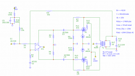
Many of my friends have built the following design:
https://www.dropbox.com/s/o6i7ofcfexpwlou/EL34_6F12P_PP.GIF?dl=0
The test results of this amplifier are here: (first are for UL):
https://www.dropbox.com/s/gahw2em2u0wfszz/EL34_tulokset.gif?dl=0
The output transformer I have used is 4k to 8 (Indel TGL40/001), but I assume 5k Tamura will perform almost identically
I have used simple Dynaco-style topology a lot with very good results.
Many of my friends have built the following design:
https://www.dropbox.com/s/o6i7ofcfexpwlou/EL34_6F12P_PP.GIF?dl=0
The test results of this amplifier are here: (first are for UL):
https://www.dropbox.com/s/gahw2em2u0wfszz/EL34_tulokset.gif?dl=0
The output transformer I have used is 4k to 8 (Indel TGL40/001), but I assume 5k Tamura will perform almost identically
Some sort of loop feedback is in order, when UL mode "finals" are employed. It's a damping factor thing. The 30 W. rating of the Tamura O/P "iron" rules a design containing a global NFB loop out. No magnetic headroom is available. Therefore, you come down to a "Baby Huey" using EL34s.
Contact Ian (GingerTube) and get his thinking. A line stage with gain may be necessary. EL34s require more drive than "12" W. types and 7591s.
Contact Ian (GingerTube) and get his thinking. A line stage with gain may be necessary. EL34s require more drive than "12" W. types and 7591s.
Last edited:
I cannot find any reason not to use UL. Some prefer the "sound" of triodes; without giving offense, I am not much into the hearing evidence thing - too personal. In any case, in the circuits I have used distortion for UL at say 90% of maximum triode output was always equal to or lower than that for triodes, plus the advantage of UL giving more headroom.
Depending on how Tamura defines the maximum output rating, you might also consider the use of 6L6GCs with lower heater current. My personal favourite topology would be a pentode input stage (EF86 or such) followed by a l.t.p. (Long-tail pair) phase inverter. From the valves listed, an ECC81 or ECC88.
Depending on how Tamura defines the maximum output rating, you might also consider the use of 6L6GCs with lower heater current. My personal favourite topology would be a pentode input stage (EF86 or such) followed by a l.t.p. (Long-tail pair) phase inverter. From the valves listed, an ECC81 or ECC88.
Check out the Turner 5050 PP UL, you can scale the design down to 30W using the Tamura OPT.
Thanks for all of the responses!
Here's a bit more information on the Tamura OT:
After checking the data sheets, the KT88 in triode mode at 422V is using 94mAx2, which seems a bit too close to the 100x2 limit. Looks like I should just stick to EL34s for this amplifier.
kward, I'm definitely getting the message that optimizing for one tube and mode of operation makes more sense.
artsalo, I've been intrigued by the Dynaco designs as they seem relatively simple, although the gain-stage phase inverter combination (in the 7199 and 6AN8 amps) don't seem to be as well regarded. Have you found any limitations on that aspect of the circuit?
Eli, I'm a little confused on the global NFB magnetic headroom issue. It looks like the three Japanese designs all use global NFB, even using higher powered tubes like the KT120 with 45W output. Is this poor design given the 30W rating of the tube? Also, I see a feedback loop on Baby Huey from the output transformer to the phase inverter. Is the Baby Huey feedback not considered global?
Johan, good to know on the UL. I'll have to check how many EF86s I have on hand. It may not be more than one or two. But I do have a bunch of 6AU6s and the previously mentioned 6AN8 (with a pentode section).
jazbo8, that Turner design is quite nice. Looks like it's a well-considered design.
Here's a bit more information on the Tamura OT:
Impedance: 5K:0-4-8-16
Freq. response (-2dB): 10-100K
Power: 30W
Primary max current: 100mAx2 (balanced), 8mA (unbalanced)
Primary Inductance (H): 170H (0mA DC), 100H (10mA DC)
Weight: 5kg
Freq. response (-2dB): 10-100K
Power: 30W
Primary max current: 100mAx2 (balanced), 8mA (unbalanced)
Primary Inductance (H): 170H (0mA DC), 100H (10mA DC)
Weight: 5kg
After checking the data sheets, the KT88 in triode mode at 422V is using 94mAx2, which seems a bit too close to the 100x2 limit. Looks like I should just stick to EL34s for this amplifier.
kward, I'm definitely getting the message that optimizing for one tube and mode of operation makes more sense.
artsalo, I've been intrigued by the Dynaco designs as they seem relatively simple, although the gain-stage phase inverter combination (in the 7199 and 6AN8 amps) don't seem to be as well regarded. Have you found any limitations on that aspect of the circuit?
Eli, I'm a little confused on the global NFB magnetic headroom issue. It looks like the three Japanese designs all use global NFB, even using higher powered tubes like the KT120 with 45W output. Is this poor design given the 30W rating of the tube? Also, I see a feedback loop on Baby Huey from the output transformer to the phase inverter. Is the Baby Huey feedback not considered global?
Johan, good to know on the UL. I'll have to check how many EF86s I have on hand. It may not be more than one or two. But I do have a bunch of 6AU6s and the previously mentioned 6AN8 (with a pentode section).
jazbo8, that Turner design is quite nice. Looks like it's a well-considered design.
The Dynaco design is excellent for UL operation, but changing to a long-tail pair phase inverter will improve performance with triode outputs. There are a number of PCBs available with this circuit, all in the original Dynaco PCB size. With a pentode front-end, this is the traditional Mullard circuit. A triode will provide enough gain, since the phase inverter has gain, unlike the split-load inverter in the Dynaco circuit.
Eli, I'm a little confused on the global NFB magnetic headroom issue. It looks like the three Japanese designs all use global NFB, even using higher powered tubes like the KT120 with 45W output. Is this poor design given the 30W rating of the tube? Also, I see a feedback loop on Baby Huey from the output transformer to the phase inverter. Is the Baby Huey feedback not considered global?
"Baby Huey" uses short loop NFB. The O/P trafo is outside the loop.
In a design, like "El Cheapo", that employs a GNFB loop, which encompasses the O/P "iron", a distinct vulnerability to core saturation exists. O/P trafo core saturation can occur, when the LF error correction signal tries to "flatten" deep bass response and any infrasonic noise that is present exacerbates matters. For a 30 W. design that uses GNFB, the O/P trafo needs to be rated for at least 45 W. and 60 W. would be better.
Attachments
Usually the coupling caps are selected to limit the overall gain at the lowest frequencies - if the output transformer is rolling off, the feedback is decreasing and the gain is INCREASED, making transformer saturation more likely if very low frequencies are present. Fortunately, there is little content in music below 40 Hz - low E on a string bass.
The low end of the transformer is set by its inductance, which is not a fixed value - it generally increases with signal level up to the saturation point. Imbalance in the output tubes will reduce inductance and degrade bass performance.
The low end of the transformer is set by its inductance, which is not a fixed value - it generally increases with signal level up to the saturation point. Imbalance in the output tubes will reduce inductance and degrade bass performance.
Hi All,
Slowly moving on this project. I've settled on Bandersnatch's exolinear amp as a starting point, to avoid global negative feedback loops that Eli cautioned as a potential problem with my output transformers. The exolinear feeds the phase inverter from the UL taps on the transformer.
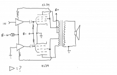
Now I'm looking at the phase inverter specifics. The above amp, along with many others like Baby Huey and El Cheapo, uses a differential pair with a CCS, so that appears to be the favored approach. Research indicates that a differential pair implemented with standard triodes will likely not have enough gain for EL34s, especially if using some vintage sources.
With that said I'm looking at the following possible phase inverter implementations (please see attached picture with generic gain stages):
Thanks for any help!
Slowly moving on this project. I've settled on Bandersnatch's exolinear amp as a starting point, to avoid global negative feedback loops that Eli cautioned as a potential problem with my output transformers. The exolinear feeds the phase inverter from the UL taps on the transformer.
Now I'm looking at the phase inverter specifics. The above amp, along with many others like Baby Huey and El Cheapo, uses a differential pair with a CCS, so that appears to be the favored approach. Research indicates that a differential pair implemented with standard triodes will likely not have enough gain for EL34s, especially if using some vintage sources.
With that said I'm looking at the following possible phase inverter implementations (please see attached picture with generic gain stages):
- Pentode:
Bandersnatch has used 6AU6 and 6AC7 pentodesHe also mentioned in another post somewhere that cascode might be even better than pentodes - Cascode:
Allen Wright's PP-1C triode EL34 with ECC88 cascodePP-2C triode KT88 with 6H30 - Hybrid Cascode:
Using triode as upper device + mosfet/jfet as lower deviceI've seen some discussion of this approach, including Merlin's Hifi Preamp Book, but few schematics of actual amps
Thanks for any help!
Attachments
There was a big thread about a KT 88 UL amplifier in here in the Mullard 5-20 style. Unfortunately, it seems the gain was not enough to apply 20db of feedback and have good input sensitivity too.... Pity, it was going very well.
if you want lots of gain, use a beefier pentode input like the 12by7 or video pentodes, ala HK Citation 5 and then run the 12AT7's at higher voltage and using ccs for tail currents....capacitor coupled first stage to LTP, then cathode followers ala Marantz 9....
if you have no aversion to sand, the cathode followers can be replaced with mosfet source followers......
i would even have G2 and G1 regulated instead of UL....
You know this design ?
http://www.triodedick.com/monobill/monobill schema versterker.GIF
I have build it and modified it heavily. Ot works well with just one tube as splitter/driver. Tube rectification is highly desirable, ideally split and separated for driver and power tubes and per channel. 5c3s are very good.
If you want the ultimate thing, use four el34 per channel in triode mode with g3 connected to anode.
Last edited:
Thanks for the responses all. I think the Mullard 5-20 is out as it appears to require a fair amount of global NFB and my transformers don't have the magnetic headroom necessary, per Eli's earlier post. Same for Dynaco.
Shef, Blitz, both of those designs look closer to what I'm thinking. Where I'm struggling is with the best components for the phase inverter (pentode, cascode, hybrid-cascode) for adequate gain with low distortion.
I'm certainly not averse to using solid state components. Planning to have solid state CCS on the phase inverter. Will test solid state cathode followers as well. Also considering full voltage regulation.
do not disregard what you do not understand, study it carefully please..
several years ago, i made a triode wired 16 KT88 pp amp....
i used the plain mullard type front end,
although i made provisions for global negative feedback,
on hearing the amp play, i found i did not need any....
i learned that triode mode and paralleled plates make for a very low plate resistance negating the need for global negative feedback, yes you can do it too....
You know this design ?
http://www.triodedick.com/monobill/monobill schema versterker.GIF
I have build it and modified it heavily. Ot works well with just one tube as splitter/driver. Tube rectification is highly desirable, ideally split and separated for driver and power tubes and per channel. 5c3s are very good.
If you want the ultimate thing, use four el34 per channel in triode mode with g3 connected to anode.
Attachments
- Status
- This old topic is closed. If you want to reopen this topic, contact a moderator using the "Report Post" button.
- Home
- Amplifiers
- Tubes / Valves
- PP Amplifier Advice Sought: EL34/KT88 UL/Triode