Can you show me that this is true?The dominant mechanism for vibrating the cabinet is the reaction of the baffle to the vibrating drivers.
Not a measurement but a pretty straightforward thot experiment.
Energy radiated from only the back of the driver thru a lossy coupling mechanism (air + damping (+ energy loss thru vent, if the box has a hole in it)) vrs all of the directly coupled energy (at the basket) from both directions of the driver movement.
If all of the rear radiation of the driver was directly coupled to the box (certainly not the case) then that source of energy would be 1/2 of that directly coupled to the box.
dave
Link to paper by Andrew Jones, formerly with TAD Pioneer, on decoupling drivers, with accelerometer tests
http://www.linkwitzlab.com/Driver Decoupling.doc
http://www.linkwitzlab.com/Driver Decoupling.doc
Can you show me that this is true? I see this assertion come up, but haven't seen it measured. If it is true, why is there not more focus on it (by perfectionists and in megabuck systems)?
Air to structure (and structure to air) coupling is very poor because of the vast difference in impedance between the two domains. But the speaker itself is a structure and its coupling is structural to structural so its coupling efficiency is going to be many times greater than the air to structure from the rear sound radiation. Hence I have always understood the mechanical vibrations of the enclosure to be the bigger deal than acoustic excitation.
I'd rather dampen these vibrations than "isolate" them. To isolate them you have to allow the speaker some freedom of movement. This can cause other problems in the response that are worse than what you are trying to fix.
Link to paper by Andrew Jones, formerly with TAD Pioneer, on decoupling drivers, with accelerometer tests
http://www.linkwitzlab.com/Driver Decoupling.doc
That's good info, thanks for the link.
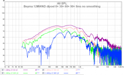
Where did this idea that OB baffles don't diffract come from? They certainly do diffract. The wave don't cancel at the edges, there is an enormous velocity gradient at the baffle edge. The pressure cancels in the plane of the baffle but there will still be a wave sent off from the edge elsewhere.
It is overruled by dipole cancellation - it must be because I can't see diffraction ripples in (off-axis) measurements, below dipole peak! A multiway dipole should be crossed so that each unit is lowpassed just above dipole peak, except the tweeter naturally.
Attachments
I did a few tests with an existing cabinet. This was built to satisfy many of the typical 'rules'
- good quality hardwood ply
- heavily built (all walls are double layer)
- well braced
- moderately stuffed
- airtight
All tests used the same volume settings and mic position
- mic suspended, 60 cm above a mini speaker
- mini speaker pointing sideways (90 degrees to the mic)
- I rolled off the lows to get a ~flat baseline (the free air test)
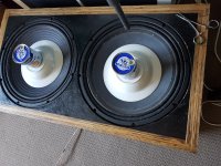
First test was to remove the 15" midbass drivers from my heavy ply cabinet, and drop this cabinet face down on top of the mini speaker. The box and carpet won't make a perfect seal, but ideally this is a test of how much sound leaks through the cabinet walls.
Next, I positioned the cabinet face up. I put the mini speaker inside the ply box, pointing into a corner, and loaded the 15" drivers back in. This is a test of how much sound leaks through the drivers.
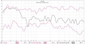
The first graph, "Moderate stuffing tests" shows these results. MUCH more sound leaks through the cones than through the cabinet.
What I take from this: if you're using a midbass or wideband driver in a 'normal', well made box, the backwave that exits the cone will probably be worse than any cabinet radiation. In light of this, my fussing over minor construction points seems a bit silly.
If you do have a suitable box handy, please replicate this test and post your results. If yours 'eats' the backwave better than mine, I'd like to copy your ideas.
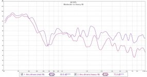
I tried lots more stuffing, in particular packing loose wool and woolen clothing around the mini speaker. That gave some benefit, mostly above 1500Hz.
This is shown in the 2nd graph, "moderate vs heavy fill".
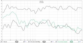
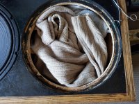
My last test was to take attenuation to an absurd extreme. The third graph, "Overkill" shows this. Even in this scenario, there's a lot more midrange leaking through the cones than through the box.
The images show the "overkill" test, where the box is packed with stuffing, as described. The drivers are largely covered and weighted down with ~500g each. It would be very difficult to get more attenuation than that, but the leakage is still high, relative to the radiation from the cabinet.
- good quality hardwood ply
- heavily built (all walls are double layer)
- well braced
- moderately stuffed
- airtight
All tests used the same volume settings and mic position
- mic suspended, 60 cm above a mini speaker
- mini speaker pointing sideways (90 degrees to the mic)
- I rolled off the lows to get a ~flat baseline (the free air test)
First test was to remove the 15" midbass drivers from my heavy ply cabinet, and drop this cabinet face down on top of the mini speaker. The box and carpet won't make a perfect seal, but ideally this is a test of how much sound leaks through the cabinet walls.
Next, I positioned the cabinet face up. I put the mini speaker inside the ply box, pointing into a corner, and loaded the 15" drivers back in. This is a test of how much sound leaks through the drivers.
The first graph, "Moderate stuffing tests" shows these results. MUCH more sound leaks through the cones than through the cabinet.
What I take from this: if you're using a midbass or wideband driver in a 'normal', well made box, the backwave that exits the cone will probably be worse than any cabinet radiation. In light of this, my fussing over minor construction points seems a bit silly.
If you do have a suitable box handy, please replicate this test and post your results. If yours 'eats' the backwave better than mine, I'd like to copy your ideas.
I tried lots more stuffing, in particular packing loose wool and woolen clothing around the mini speaker. That gave some benefit, mostly above 1500Hz.
This is shown in the 2nd graph, "moderate vs heavy fill".
My last test was to take attenuation to an absurd extreme. The third graph, "Overkill" shows this. Even in this scenario, there's a lot more midrange leaking through the cones than through the box.
The images show the "overkill" test, where the box is packed with stuffing, as described. The drivers are largely covered and weighted down with ~500g each. It would be very difficult to get more attenuation than that, but the leakage is still high, relative to the radiation from the cabinet.
Attachments
Fair question. What would you measure that separated the two mechanisms? OK that is perhaps something of an unfair question given the relevance you are currently assigning to your measurements.> The dominant mechanism for vibrating the cabinet is the reaction of the baffle to the vibrating drivers.
Can you show me that this is true? I see this assertion come up, but haven't seen it measured.
An engineer would tend to consider the physics of the situation and estimate bounds for the relative power being pumped into the cabinet by the driver and by the air within the cabinet. This needs an estimate for an average force and an average velocity.
The force from the driver is simply Newtons second law: the product of the moving mass (cone assembly plus air and available from spec sheet) and it's acceleration. The velocity is that of the baffle around the bolts.
The air is a bit trickier:
* At low frequencies and for a sealed cabinet the air will behave as a discrete spring and the average pressure on the cabinet walls will follow from the volume of air displaced by the cone, the volume of the trapped air in the cabinet and the average air pressure in the cabinet. Note this force is proportional to displacement whereas the force by the driver is proportional to acceleration (frequency squared times the displacement) and so it is likely to be only be relevant at low frequencies.
* At higher frequencies the compression of the air around the driver to create sound will start to become the dominant effect. The acoustic pressure will scale on the cone velocity and the acoustic impedance of the air (product of air density and speed of sound). This pressure will reduce in magnitude as the surface area of the sound wave grows away from the cone. So an estimate of the upper bound on the average pressure on the inside of the cabinet would follow from the ratio of the cone area to the internal cabinet area times the average pressure at the cone (in reality it will be less due to dissipation by the damping material and the pressure varying over the surface over the cabinet). Note this "sound" average force is scaling with velocity which is what will make it become larger than the "spring" average force at high frequencies. But it will be getting relatively smaller with frequency compared to the "driver" average force with is scaling with acceleration.
This gives us reasonable and straightforward to calculate estimates for the average force in the two cases. It leaves us needing an estimate for the average velocity of the cabinet at the bolts and an average velocity over the surface of the cabinet. We could estimate they are the same and come up with numbers but pulling things together like this has told us a fair bit about how to keep vibration out of a speaker cabinet (but not how to get rid of what does enter) :
* Stiffening the baffle will reduce the power pumped in by the drivers. This is sufficiently important that serious speaker companies will often use metal baffles even at the cost of little damping.
* Stiffening the rest of the speaker cabinet would reduce the power pumped into the cabinet by the internal air. This might become significant at low frequencies. It's importance is debatable given the wavelengths at low frequencies.
Megabuck audiohile systems are often technically daft because it is not important in providing what rich audiophiles want to buy. If you wish to get a feel for what is technically wise in high performance speakers then it is perhaps better to look at what the conservative large pro companies do in their top of the range products (e.g. stiff baffles, not obsessive about cabinet stiffness, good amount of damping).If it is true, why is there not more focus on it (by perfectionists and in megabuck systems)?
Linkwitz's knowledge is good in some areas but less so in others and he has become a bit more subjective with age. Yours is an example of an area where he is relatively weak. But note he fairly swiftly recognised the issue and fixed it. He didn't try to deny it as many would just a bit of subjective face saving. He may not be perfect but he is very much at the good guy end of the speaker DIY spectrum.e.g. Linkwitz will sell you a kit for to 'fix' this, but there's no measurements given, just some subjective talk - based on a sighted and very delayed A/B test.
ORION Revision 1
"What is the sonic benefit? Well, it does not jump out as something you immediately point to"
I don't think you are getting much agreement from the posters here with the "does a good job of isolating one part of the problem" aspect. The experiment is simply too unrepresentative of how a speaker cabinet vibrates in operation. You can see this by comparing your measured spectra with those from the various publications that have been cited. In these you can see a stiffness controlled region at low frequencies, a few large low frequency modes and an increasing density of less energetic modes at higher frequencies. The details may vary from case to case but this physics must be present.This is why I like the test. It does a good job of isolating one part of the problem, and getting some comparative test info that shows some material based differences.
I suspect you might be showing that it is not that easy but it is good to see you having a go. To improve significantly on what one can get from a careful knuckle rap test will require a lot of effort but looks doable.I think it is good to know that, with DIY gear, one can easily show the correlation between the technical data about a material, and how it radiates sound when used in a box.
This post is huge. I am of course wasting time on the web to avoid doing what I should be doing: my tax forms.
There was a similar discussion here: The Science of Speaker Cabinet Design - AVS Forum | Home Theater Discussions And Reviews. What I found meaningful from that discussion was the need to treat the problem as different for different frequency regions. For example, below the cabinets resonant frequencie(s) (not talking about the box tuning of the air volume), stiffness is probably most effective. At the resonant frequencie(s), damping is probably most effective, and above the resonant frequencie(s) possibly mass and damping.
I don't think you are getting much agreement from the posters here with the "does a good job of isolating one part of the problem" aspect. The experiment is simply too unrepresentative of how a speaker cabinet vibrates in operation. You can see this by comparing your measured spectra with those from the various publications that have been cited. In these you can see a stiffness controlled region at low frequencies, a few large low frequency modes and an increasing density of less energetic modes at higher frequencies. The details may vary from case to case but this physics must be present.
Can you post specifically what your referring to in the cited literature? I think there is plenty of potential in Hollowboy's measurement, although i don't know the specifics of his setup very well. Still, it seems to have more going for it than a knuckle rap test!
Connect the terminals on the dummy speaker together to simulate the "control" (not an EE here!) of the amp in normal operation.
I restored the cabinet to moderate stuffing, and gave this a go (I plugged the dummy woofers into another amp).
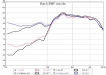
The "control" appears to be very important at LF but is insignificant by 200Hz.
The attachment shows the results with and without a high pass filter on the mini speaker.
I got the same result with different volume levels, mic positions, etc. I did not test below 100Hz since the sound generator is a mini speaker and I didn't want to blow it up... but that's low enough for the trend to be obvious.
I'd be interested to see others repeat this check with their own gear.
Attachments
although i don't know the specifics of his setup very well.
it is basically the same as the picture in post one, except my large cabinet has driver cutouts.
A) Face down (with no woofers) I can measure sound leakage that is almost entirely through the cabinet.
B) Face up (with woofers) I can measure sound leakage that is almost entirely through the woofer cones.
B) is a lot higher than A) and therefore seems B) much more important to mitigate.
The test is simple, and I encourage others to try it. I'd like to see a (reasonably portable, and living room friendly) system where B) is better.
I had known about Audioqualia. Didn't knew about lenco thread. Thanks for that.For turntable plinth damping, a few applicable links:
Lenco Reference :: Damping factors
audio qualia - Index page
What I was interested in is the 'technique' used to fill microspheres between two panels. To keep two panels connected some solid connection has to be made so vibrations does travel to other panel. Whereas with CLD on other hand has damping material glued (?) to both separate panels. (Both panels not touching/coneected to each other). So damping/dissipation might be more.
Regards
I can expand on the 3 things I mentioned. When a measurement is taken it is normal to check it is valid. One way to do this is check that what technical knowledge tells you should be present actually is present. So at frequencies below the first resonance the vibration is stiffness controlled and so should roll-off at a predictable rate like a speaker in a box. The lowest frequency resonances are the most distinct and typically contain the most energy. Individual ones may have mode shapes that aren't excited by the forcing or have a null where the mic is located but most will not. At higher frequencies lots of modes get excited which smooths the variation in the response. All this needs to be present if the measurement is to be of the sound radiated by the cabinet and indeed it can be seen in the publications from the BBC, KEF,...Can you post specifically what your referring to in the cited literature?
Now the measurements being shown are clearly not of the sound radiated by the cabinet of an operating speaker. So what are they? And do they tell us something useful?
Potential to do what? If measurements of this kind might be useful for engineers designing speaker cabinets why do you think they are not currently widely used? I am not intending to have a dig and it is good to see the OP performing experiments, wanting to read the literature and being prepared to decide and dismiss.I think there is plenty of potential in Hollowboy's measurement, although i don't know the specifics of his setup very well.
In its current form it measures nothing that I can see that helps an engineer in assessing the performance of a cabinet or showing where improvements might be found. Not saying it doesn't just that I can't see it. Would be good to be shown otherwise.Still, it seems to have more going for it than a knuckle rap test!
A knuckle rap test does provide useful information. It won't provide the forced response of the cabinet with the drivers operating but it can provide information about the modes that response is built on. It will provide the frequency and damping of the main modes. The damping is particularly useful in supporting simulations because the damping of a full assembly is difficult to specify because of the significant role of joints, bolts,... in addition to the damping of the materials. If an engineer can identify a problematic mode then doing something about it is often straightforward (e.g. KEF paper on LS50).
Interesting I had a vision of gauging somehow through vibration, but not of a simulated method to actually listen to its audible effects.
The last sub Im working on I made every panel 1.5" birch ply, thinking I could remove any more possible room for doubt by way of colouration.
Or a high speed camera, but again that will only show you if the cabinet walls have movement.
The last sub Im working on I made every panel 1.5" birch ply, thinking I could remove any more possible room for doubt by way of colouration.
Or a high speed camera, but again that will only show you if the cabinet walls have movement.
at frequencies below the first resonance the vibration is stiffness controlled and so should roll-off at a predictable rate like a speaker in a box. The lowest frequency resonances are the most distinct and typically contain the most energy. Individual ones may have mode shapes that aren't excited by the forcing or have a null where the mic is located but most will not. At higher frequencies lots of modes get excited which smooths the variation in the response. All this needs to be present
the damping of a full assembly is difficult to specify because of the significant role of joints, bolts,... in addition to the damping of the materials.
To me, it looks like the 3rd point I underlined explains the earlier points: my experiments are tests a full assembly containing different materials. So are the tests in the two pages I linked (Ludwig's page and Csaba's page).
Materials aside: my experiments indicate that the rearwave emerging through the cone of my moderately stuffed box are 10-15dB louder than the rearwave that emerges through the cabinet (first graph, post 127). That's an enormous difference.
Around 300Hz, it is even worse / and harder to reduce. That seems like the thing to focus on.
...but maybe my methodology was flawed, and the real difference is 'only' 8-13dB
")
Why don't you try it yourself? It takes less than an hour. The only awkward bit is removing and replacing the woofer(s).
So far, what I've taken from this thread and my tests is that building a decent box is a fine idea, but an even better idea would be (subs +) a configuration that eats, ignores, delays or dissipates the backwave much more effectively than a typical box does (maybe a 'boffle' cabinet, compression drivers, etc).
So far, what I've taken from this thread and my tests is that building a decent box is a fine idea, but an even better idea would be (subs +) a configuration that eats, ignores, delays or dissipates the backwave much more effectively than a typical box does (maybe a 'boffle' cabinet, compression drivers, etc).
Next step: looking (again) at info on the precedence effect / auditory masking (temporal), because "it is unwise to spend time or money chasing after criteria which are not perceivable in the end product."[1] Since some leakage of the backwave is inevitable, I want to know: what's the easiest (+ cheapest + most compact) way to mask it, so the backwave becomes non (or less) perceivable?
Based on a little reading + listening, it seems that delays >2 ms are good (for masking), and for delays up to 20ms "reflections must be less than about 15 dB to be subjectively inaudible" [2]
If a closed box is ~40cm deep, without large obstructions, the 1st reflection off the rear of the box should be delayed >2ms,* however, my own tests indicate the other part - 15dB of backwave attenuation - cannot be achieved, especially below 400Hz (graphs 1&2, post 127). Lots of other tests have shown that box stuffing is ~useless in this range, so I see little reason to doubt this finding. This rules out 'normal' boxes.
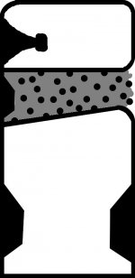
Therefore, to achieve >2ms delay and 15dB of attenuation, the simplest method seems to start with a 'normal' box, and add a heavily stuffed line (~40cm long, tapered, 0open ended) to 'eat' the rearwave of the midbass driver.
- If the rearwave has to travel 1 metre further than the frontwave before hitting the listening position, that's ~3 milliseconds of delay.
- lots of scattering should give a lot of attenuation.
...so I'm thinking of something like this crude picture. Ideally, it'd cross to bass drivers somewhere around ~100Hz, and they'd be used in some form of opposed configuration (opposing sides or PPSL).
[1] Geddes / Lee
[2] David Howard and Jamie Angus (Acoustics and Psychoacoustics)
the quotation is maybe out of context; they are discussing directionality. Feel free to point me at better info.
*other configurations would do this (or better)
- an OB >1m wide
- front loaded horns to 100Hz
- a soffit mounted IB
...but all are impractical / much too room dominating.
Attachments
I would think the amount of attenuation needed varies with frequency? With lower frequencies being more forgiving as it seems kind of difficult to judge what a 2ms reflection means when it takes 6ms (for example) to form a single cycle of the tone?
BTW I would still try use quasi-anechoic measurement methods here. Flipping the box around to get different measurements changes how it interacts with the room and you won't be comparing apples to apples anymore. So either use gated or close mic techniques.
BTW I would still try use quasi-anechoic measurement methods here. Flipping the box around to get different measurements changes how it interacts with the room and you won't be comparing apples to apples anymore. So either use gated or close mic techniques.
I want to know: what's the easiest (+ cheapest + most compact) way to mask it, so the backwave becomes non (or less) perceivable?
I’d suggest an aperiodic TL (a subset of what you have drawn)… suck the backwave down the line and damp the heck out of it.
We have had good success with this for the midTweeters in our WAW (formerly called FASTs)
dave
- Status
- This old topic is closed. If you want to reopen this topic, contact a moderator using the "Report Post" button.
- Home
- Loudspeakers
- Multi-Way
- Measuring sound output from speaker cabinet walls