Hi- well this grew into more description than I planned on-
I haven't done anymore on this yet but for now I do have some more photos and some measurements of the value of the strain gauges that may be of interest.
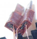
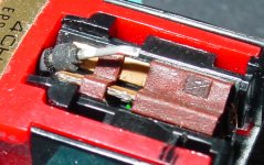
One picture shows the strain beam that went open recently. The one with the burnt wire or possibly corroded wire. No clue yet what happened. It was unused in a box for the last 5 years and when I re-measured it the resistance went high and open right in front of my eyes. It measured normal for about 1 second. I can't imagine it is the meter. Plenty to check on before an answer.
I have 4 bodies and did these measurements 5-6 years ago. Full cartridges were purchased in 1981, 1983 and about 1988, all new. 3 direct from a Panasonic electronics dealer. They were cheap then.
1= 875R and 895R
2= 888R and 1035R I think this is the one that went open and is pictured here. I need to confirm that.
3= 774R and 779R
4= 796R and open. This is the one the top plate fell off of in 1990 so has never been used.
The strain gauge beam material does not look like phenolic circuit board that I have seen but that does not mean a thing. One picture shows the metal wrapping around the ends unlike PCB material I have seen. I hope it is not some custom tweaked composite a couple of guys spent years perfecting! Also the actual chips looks hand soldered on. How do you keep it from being prestressed from the installation? So I would guess the strain beams were all measured and matched into pairs.
Also I notice a different radius or angles on the ends. I will need to check each cartridge again and focus on that area. There are so many different positions of the rubber coupler on the stylus shaft I have seen I could not say which is correct or what difference it makes. Several seem to contact the edge of the beam rather than lie parallel to the beam.
I think I would also like to measure the strain gauges before and after relieving all pressure off them from the body mounting. I will measure the good one in the photo above since it is now loose. The small plastic piece on the under side of the body nose simply squeezes (gently) the brown rubber mounts between the 2 body moldings.
I can also imagine a lot of changes by moving the short rubber brown front mount up or down the strain gauge end.
There are so many variables and these things getting rare that I myself would also consider another option from remounting in a new body, rather a custom mount that has a heavy mounting plate for mass and some way to gently envelope the whole original cartridge, such as a strap from shim material, maybe a plastic roughly heat formed to the cartridge shape, to minimize resonances and it could also serve as a clamp for the stylus. No alteration of the original cartridge. That and tuning up each cartridge with careful re-adjusting of the strain beam positions and accurate stylus mounting within the existing body.
If new materials can be found - well that is an exciting idea!
I haven't done anymore on this yet but for now I do have some more photos and some measurements of the value of the strain gauges that may be of interest.
One picture shows the strain beam that went open recently. The one with the burnt wire or possibly corroded wire. No clue yet what happened. It was unused in a box for the last 5 years and when I re-measured it the resistance went high and open right in front of my eyes. It measured normal for about 1 second. I can't imagine it is the meter. Plenty to check on before an answer.
I have 4 bodies and did these measurements 5-6 years ago. Full cartridges were purchased in 1981, 1983 and about 1988, all new. 3 direct from a Panasonic electronics dealer. They were cheap then.
1= 875R and 895R
2= 888R and 1035R I think this is the one that went open and is pictured here. I need to confirm that.
3= 774R and 779R
4= 796R and open. This is the one the top plate fell off of in 1990 so has never been used.
The strain gauge beam material does not look like phenolic circuit board that I have seen but that does not mean a thing. One picture shows the metal wrapping around the ends unlike PCB material I have seen. I hope it is not some custom tweaked composite a couple of guys spent years perfecting! Also the actual chips looks hand soldered on. How do you keep it from being prestressed from the installation? So I would guess the strain beams were all measured and matched into pairs.
Also I notice a different radius or angles on the ends. I will need to check each cartridge again and focus on that area. There are so many different positions of the rubber coupler on the stylus shaft I have seen I could not say which is correct or what difference it makes. Several seem to contact the edge of the beam rather than lie parallel to the beam.
I think I would also like to measure the strain gauges before and after relieving all pressure off them from the body mounting. I will measure the good one in the photo above since it is now loose. The small plastic piece on the under side of the body nose simply squeezes (gently) the brown rubber mounts between the 2 body moldings.
I can also imagine a lot of changes by moving the short rubber brown front mount up or down the strain gauge end.
There are so many variables and these things getting rare that I myself would also consider another option from remounting in a new body, rather a custom mount that has a heavy mounting plate for mass and some way to gently envelope the whole original cartridge, such as a strap from shim material, maybe a plastic roughly heat formed to the cartridge shape, to minimize resonances and it could also serve as a clamp for the stylus. No alteration of the original cartridge. That and tuning up each cartridge with careful re-adjusting of the strain beam positions and accurate stylus mounting within the existing body.
If new materials can be found - well that is an exciting idea!
Attachments
These are great photographs, nice to be able to see the design details close up. Several people have approached me and offered to source new bodies if someone could provide mechanical drawings of the internals of one of these cartridges, this is well above my pay grade unfortunately - electrical engineers don't necessarily make good mechanical engineers, and I'm truly horrible. 
They are part of the cartridge compliance, but they are not actually the dominant compliance which is the compliance of the transducers (they flex obviously) and the decoupling and mounting arrangement at the far end. The forward-most one couples the cantilever to the transducers.
The first block on the transducer I suspect controls the lateral/horizontal compliance, and the vertical is controlled by the transducer decoupling and mounting arrangements.
The stylus assembly does not control cartridge compliance unlike typical magnetic cartridges, the styli are fully interchangeable and the compliance of the cartridge does not change significantly regardless of the stylus used.
The one on the left is a Sound Smith replacement stylus for their strain gauge cartridge.
Regarding -24V Bias Supply
Some pages back I suggested changing a resistor value to trim the -24V supply a bit closer to the target voltage if you like me measured something over -24V. I recommend rather than adjust for -24V you either leave it alone or trim for -25V.
Due to tolerances in my regulator I ended up with -25.4V on the bias supply, and it turns out that it sounds just a bit better at the higher negative bias. I am not able to pin it to anything specific, but it affects both the operating point on the output and the performance of the subtraction CCS on the front end. (I'm too lazy to bother hacking up the boards and trying to identify the most relevant shift in operating point, but both are probably significant as the shift in both is > 4% in mine.)
I would however not allow it to go more negative than -26V, unless you enjoy the prospect of popped jfets in the event of a "disconnect accident" with the power on.
As also noted elsewhere R7 on the audio PCB can be profitably reduced from the original 100 ohms to a range of 33 - 56 ohms. Use a high quality metal film here.
Edit: I have attached an updated schematic with the most current recommended configuration.
Attachments
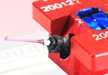
Getting ready for local audiofest here in 2 weeks so I have been working to make sure the system is fully up to snuff. I've updated the room eq., replaced the GM70s in the power amps, and done some additional tweaking on the main strain gauge pre-amp and the cartridge mounting arrangement. (HS-5, copper and cocobolo spacer, blue blob)
I am using a Panasonic OEM stylus which is more sensitive to both SRA and cleanliness than the Bliss that I also like. Set up properly this stylus may be very slightly better than the Bliss, there is a little more air around the highs, and it sounds very slightly cleaner overall. It also is quite unforgiving and mistracks quite gracelessly as schmutz builds up between the record and the bottom of the flat where the stylus is mounted. I would estimate the mass of the OEM stylus to be less than half that of the Bliss, and this results in noticeably better highs in some circumstances.
I think I am going to spring for one of Peter Riggle's VTAF devices shortly as this will allow me to adjust the VTA on the Schick on the fly. It should make finding the sweetspot quite a bit easier, when you are there it's obvious, when you are not it isn't until you are far off the mark.
I have done some significant A/B listening on some material between the HAP-Z1ES and the strain gauge set up particularly with the Punch Brothers "The Phosphorescent Blues" (2496 and vinyl). The differences are quite a bit smaller than you might expect, dynamics are very similar which leaves me wondering whether the typical MC/MM cartridge and tube pre-amp actually exaggerates dynamics a bit. The strain gauge set up might provide a bit more depth, but the differences are not staggering. This is actually a relief as it means the playback is essentially accurate within the context of what it means to drag a piece of rock through a plastic groove.
I can't predict the future, but unless I hear something earth-shatteringly better I think my primary vinyl focus is going to be on extracting the best possible performance from this technology.
Thanx Dave for the photos
Thinking about how to approach a new cartridge body and the most signifcant area of a signature contribution from the plastic body, ( a blob in front does make it smoother ) is how the cantilever mounts ( resonance starts here )
The substance that holds the elements has too much surface area and is dead enough to be a serious contributor in comparison to the cantilever IMHO. Not saying it doesn,t, but my reasoning points towards the business end first and a new aluminum body sandwiching the element holder.
A " V " block with a flat bottom made with acrylic or wood to hold the elements could be pressed down in the body since machining down in a new body results in a flat surface.
Wood can always be added between the headshell ( Kevin's example ) as a bonus adjustable addition, rather than making the body completely out of wood with no options for rigidity.
I think it best to have stiffer material near the point of resonance than the opposite way
Sound smiths version seems correct in its bolts down rigidity of the cantilever assembly, and making it movable sideways would allow a perfect centering of the donut to element equalization leading to a perfectly centered cantilever as a result
No option exsists with the current design
That blue stuff in the removable stylus assembly looks to be some kind of damping compound and have seen different looking versions in there.
Your thoughts ?
Regards
David
That shibata does have a tendency towards tracing noise as you say and must be set just right.
The ultimate end is the boron or ruby option with a line contact or hyper elliptical contact patch to replace the stock examples
Kevin, what makes the 460,465 almost double the tracking force in comparison to the 451/450c2 versions ?
Are the donut / first element dampeners placed in significantly different locations ?
Regards
David
Last edited:
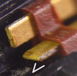
I quickly looked at the cartridge parts this morning to refresh myself on the project.
I notice a difference between the strain beams between the 2 disassembled samples.
Both are 451C but have a different number stamped on the side underneath where the stylus goes.
Not sure if that means anything at this point.
They seem to be brass rather than gold plated copper and the brass shim seems to be a different thickness between the 2.
Also the center layers seem different. One does appear similar to fiberglass board but the other is much courser. It could just be the way they were cut, or actually some edges appear sheared.
I will check out the Kulite catalog and do some more inspection.
There is a guy that already did this...and recreating these might not be cheap.
After the strain gauge and beam material is the rubber V shape mounts and front V dampener.
It might be possible to build it up from sheet material.
Avwerk - was just logging in to post and saw your comments and am leaving so I will get back to this later.
Everything appears to be pretty much exactly the same from what I can see, I believe the difference is the dampers and the relief cut into the end of the element, there could even be some differences in the material itself. The stylii are completely interchangeable regardless of the PN on the stylus, and does not alter the required tracking force or effective mass required for a given cartridge to work correctly.
I'm not eager to investigate for fear of breaking something. Also the prices have increased substantially since I bought the 451C so replacing a broken one will cost significantly more.
In terms of sonics there does not seem to be much to choose between the ones I own.
The 450C when it works (rarely) is quite different, but it has a problem and is probably headed towards the scrap heap.
They aren't perfect and exhibit some deficits, but they seem small in comparison to what they offer in comparison to much more expensive devices.
One of my areas of focus going forward a bit will be somewhat more sophisticated EQ to improve overall flatness and HF extension. I'm working on something now that looks promising but still have to build and test it.
It will plug right in but requires two existing resistors be jumpered. As an aside the current simplistic EQ works way better than anything else I tried that theoretically addressed the funky frequency response of these cartridges.
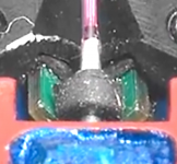
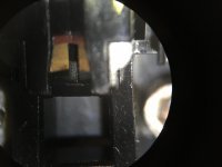
Here is resonant tip/body reduction for a stock SG cartridge.
Pull the removable stylus off and look down in the square hole of the cartridge body.
This hole is .200" deep.
The stock needle assembly reaches only .175" deep (.025" of dead space)
This is the cantilever rubber base attachment point ("U " shaped channel ) that stops short of reaching the bottom of hole when pressed in.
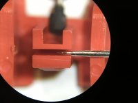
The needle points (photo) to a split lower piece with a tab protrusion on the bottom of the photo
This "tab" presses against the back side of the square hole making it more rigid- but -
The entire "U" channel with the vibrating cantilever is leveraged off this piece and the donut
/element as a fulcrum point between the record.
In effect this is a resonant chamber that needs filling...
Stands to reason this could be slightly filled with blutac on the bottom (.025" of dead space )
The "split " and part of the "U" channel can be also filled with the same material to stop this highly resonant area as you press the stylus assembly in and compress this foundation.
You can always remove it without penalty.
Tell me if you can hear a change by doing this easy mod.
Regards
David
Regards
Pull the removable stylus off and look down in the square hole of the cartridge body.
This hole is .200" deep.
The stock needle assembly reaches only .175" deep (.025" of dead space)
This is the cantilever rubber base attachment point ("U " shaped channel ) that stops short of reaching the bottom of hole when pressed in.
The needle points (photo) to a split lower piece with a tab protrusion on the bottom of the photo
This "tab" presses against the back side of the square hole making it more rigid- but -
The entire "U" channel with the vibrating cantilever is leveraged off this piece and the donut
/element as a fulcrum point between the record.
In effect this is a resonant chamber that needs filling...
Stands to reason this could be slightly filled with blutac on the bottom (.025" of dead space )
The "split " and part of the "U" channel can be also filled with the same material to stop this highly resonant area as you press the stylus assembly in and compress this foundation.
You can always remove it without penalty.
Tell me if you can hear a change by doing this easy mod.
Regards
David
Regards
Attachments
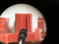
I tried part of your suggestion which was to fill the void between the front and rear tabs in a Bliss stylus. I was afraid to fill the bottom of the cavity as it seems unlikely I could get it all back out if I didn't like the subjective result.
I expect the blue tac to harden with time. I used a very, very small flat bladed driver (1/32nd of an inch) to press a tiny amount of blue tac into the groove between the tabs. I completely filled that area and trimmed away any that oozed out the sides.
The results; It certainly doesn't hurt, subtle, I have the impression of an improvement in image stability and a further improvement in resolution. Midrange stereo separation is noticeably better, slightly more neutral/restrained tonal balance.
I applied this on the 451C which is mounted on a well damped arm wand on the Souther SLA-3. This set up overall has a fuller, bassier, less analytical sound than the 465C on the Schick, and that continues to be the case, the overall tonal balance changed very subtly in a direction I frankly prefer.
In short I would recommend doing it. Your results may vary.
I just applied the same tweak to the OEM Panasonic stylus on the 465C installed on the Schick.
I would report the same general effects, again it's pretty subtle, and I regard it as a significant overall improvement. Confirm no harm.
Again I just filled the gap David points to in his photograph, and have not evaluated his other suggestions.
Filling some of the U channel may be beneficial but you probably should not allow the blue tac to come into contact with the mounting bushing - I'm concerned about possible degradation of the bushing if it reacts with something in the blue tac. (AKA Blue Stik here in the U.S.)
You could cut a small square of Sorbathane with a razor blade and drop it in the bottom.
No mess this way.
I did measure a second OEM replacement stylus as being .185" long compared to the stock version of .175" so you need to reach .200" depth
So not much needed, just the compliance of whatever Sorbothane you might have. ( my sheet was 30 durometer ) and will go in a second cartridge for comparisons sake.
The goal is coupling that U channel beam to the base any way you can get it.
Regards
David
Unfortunately no sorbothane here.. Will need to cast about for some. (Probably eBay to the rescue)
I can send you one, but I don't know the durometer for it. It is kind of soft though.
Another option would be to seal off the rubber and drop lead pellets with 5 minute epoxy into the U channel.
You might get 3 or so in there, anything to add mass along with sorbothane to couple to the body.
I have 3 cartridges and 4 replacement stylus assemblies and will try this mod next
Do not under estimate the forces going on with a cartridge !
If you could shrink yourself down to fit in a groove next to the diamond, it would be a incredible violent world so anything you can do to tame its environment will pay off in sonic dividends.
Regards
David
- Home
- Source & Line
- Analogue Source
- Playing With Panasonic Strain Gauge Cartridges (And A Dedicated Phono Stage)