Yes. just a guy seems to think that Hornresp is quite accurate:
Considering that Hornresp does not account for bends in the horn path, flexing horn-walls, turbulence around sharp edges at high spl, room acoustics (which usually change the response curve a lot more then small changes in the simulation) changes in Bl within the stroke of the driver, differences between different batches of drivers etc, I see the Hornresp sims as close enough for a reliable indication of expected performance.
The most important factor is the real life performance, and this is not a statical condition which adheres to a simulation. The response will change dramatically dependent on operating conditions, processing, the acute condition of the driver (changes gradually over the whole lifetime of the driver) and many other factors.
I have posted measurements of my ROAR12 in the ROAR18 thread.
I will take new measurements once I get my ROAR back. My friend Anders Martinsson has it on loan at the moment.
Regards,
Johannes
Yes I do think that Hornresp is quite accurate, as it has been proven over and over to be extremely accurate.
Bends in the horn path are not consequence, if you simulate using the advanced centerline method your sim will be accurate.
Flexing horn walls means you didn't build your horn right. Try some bracing.
Turbulence around sharp corners at high spl is not an issue. Hornresp is a small signal simulator. Don't attempt to use it for things it's not meant to do. Besides, your measurement is not at high power anyway so what difference does this make?
Changes in Bl have nothing to do with anything. Hornresp is a small signal simulator and is not meant to accurately sim close to or past xmax.
T/s parameter differences in different batches have nothing to do with Hornresp. If you don't enter accurate t/s you won't get an accurate simulation. Is that hard to understand? Garbage in garbage out.
You seem to think that Hornresp should be able to account for a wild variety of things it was never meant to consider. No simulator can account for all these things you list accurately, it's absurd to think they should. Hornresp is a small signal simulator.
You incorrectly state that your ROAR series has some type of advantage at high power that other tapped horns don't. Any well designed tapped horn will provide the same amount of spl and better frequency response than your ROAR series.
A flat 30 Hz response is quite brutal. Every time I hear clean bass below 35 Hz at levels above 125 dB I feel nauseous and dizzy. Tapped horns tuned that low usually get a very heavy and sluggish character that is difficult to correct with DSP.
My first ROAR-prototype is tuned to 33 Hz and it almost unusable, even though it has a great mid bass peak and punch. It tends to overwhelm everyone listening to it. It is fun to hear the pure overwhelming energy rattle everything and making your pants flap against your legs, but its a bit to overwhelming to listen to for extended periods of time.
One Swedish guy who built a hometheater sub based on the ROAR concept (large front resonator) with a B&C 12TBX100 fooled his wife that there was a helicopter hovering above their house.
Even though it is tuned to 35 Hz he has a very powerful and energetic response down to 10 Hz indoors.
These front resonator enhanced quarter wave designs does not behave like normal tapped horns or FLH. Everyone who hears them comments on their very physical and tactile quality. My ROAR12 tuned to 45 Hz used indoors makes people feel sick whenever we disable the highpass filter. It makes a great home theater sub, even though it has a 45 Hz simulated lower knee in the passband.
I would recommend a 38 - 45 Hz tuning for a B&C 18SW115-8. Raw efficiency is usually much more usable then the last few Hz of extension.
If you stack several SuperPlanar horns or ROAR18 you gain those few Hz of extension back without the penalty of lower efficiency or large unwieldy boxes.
Regards,
Johannes
This probably takes the cake for the biggest load of garbage I've ever heard.
I already showed you that I could get the same response (minus the big dip at the top of the passband) with a normal shaped tapped horn, so don't tell me these ROAR things operate differently than a normal tapped horn.
The assertion that your 12 inch ROAR is just too powerful and can't be used because it makes everyone sick is offensive on a science based forum. Your creation does not violate any laws of physics and it's nothing special in any way. In fact it's a terrible design due to the huge dip at the top of the passband.
Suggesting that it will play just fine at high power levels without a high pass filter is just simply ridiculous. Read the following quoted post from Ricci. And then read it again.
I would be extremely surprised if the output is useful any further below tune than any other system not using a closed air volume on one side of the driver. In my opinion and experience you may get a useful 1/3rd octave below tune. Perhaps 2/3rd octave or a bit more in a smaller indoor setting. If the tuning is 40Hz you could expect some useful amount of output to maybe 31.5 to 35Hz outdoors. Indoors possibly a bit under 30.
The modeling of these or any other system where the back wave is resonant will bear this out. Excursion gets out of control below tune, power handling is low, response drops off a cliff and distortion shoots through the roof. High resolution controlled measurements will back this up if they are taken.
And finally, tapped horns do NOT drop the low knee when stacked. This has been proven time and time again. It was pointed out to you in the same Danley BC sub thread where you invented the ridiculous vortex creating an extra horn segment out of thin air theory.
Here's a measurement made by Danley Sound Labs of 1 vs 4 tapped horns stacked. The low knee remains the same.
I have also worked out Ivan Beaver's measurements of the DSL-TH115 in stacks to an higher resolution to get a more precise picture.
First the original:

Second with +12dB for 1 TH115 and +6dB for dual stack:

Now for extra points here's a couple of measurements that were shown in the BC 218 thread that you either didn't understand, didn't remember or didn't read in the first place. They are all labeled so you can see what they are. They come from here - http://www.diyaudio.com/forums/subw...c-subs-reverse-engineered-24.html#post4431003


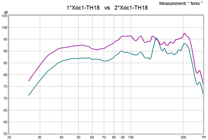

The low knee doesn't change when you stack tapped horns. It doesn't even change that much with large front loaded horns, maybe 1 or 2 hz at most. Check the data sheet for the Danley BC 218.
Listen, clearly you think I have something against you personally but I don't. I just don't like having to correct your mistakes, the same mistakes, year after year. If you had listened in the first place and learned a bit then this would not still be happening. Constantly correcting your mistakes takes a lot of time and makes me unhappy.
Last edited:
The low knee doesn't change when you stack tapped horns. It doesn't even change that much with large front loaded horns, maybe 1 or 2 hz at most. Check the data sheet for the Danley BC 218.
This measurement from the same thread suggests that the LF knee can move downwards:
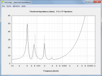
Really though it's a bit disappointing to me that impedance measurements weren't done. Those aren't subject to mike positioning issues and the like, and would definitely show if there was any downward shift, because the peaks in the impedance curve would also shift downwards.
BTW, those measurements also show that the TH115 and the SS15 both have ~10dB notches in the 100~200Hz region. Not as bad as the ROAR designs, but still
") ....
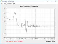
....Apart from that super-deep notch in the midbass frequencies, my other concern about the ROAR alignment is the high GD at the lower end of the passband. Some of the sims here show a GD of near 30 ms @40 Hz. Even if you assume the passband GD is 5ms (going by the GD graph), that's still 25ms. Compare to my POC3 TH that has a delta GD of around 12ms at 40 Hz. My POC4 design with its 33 Hz lower resonance frequency has a peak delta GD of 13ms in its passband. That's a pretty big difference in GD. And I'm sure other THs with similar passbands show similar GD curves.
As for the short, high GD spikes in the 100 Hz to 200 Hz region, I'm not sure that would be as audible as the wider peaks lower down in the passband. A few weeks ago I was working on an idea to come up with something more indicative of the audibility of the GD for a design by averaging the GD over an octave, and the results looked promising, but I dropped the project to work on my latest subwoofer build
.And finally, tapped horns do NOT drop the low knee when stacked. This has been proven time and time again.
Hi just a guy,
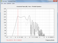
Do you have any thoughts on what might be happening here, in a practical sense? I would very much like to understand what it is about tapped horns that make them perform differently to other low-frequency loudspeakers when configured in multiples. As you know, the classical theory would suggest that the low knee should indeed drop due to the enhanced LF acoustical loading conditions (as can be readily seen in the attached simulation comparing a single tapped horn to four identical units connected in parallel).
Your comments would be appreciated, as always.
It's a real mystery to me...
Kind regards,
David
Attachments
Really though it's a bit disappointing to me that impedance measurements weren't done. Those aren't subject to mike positioning issues and the like, and would definitely show if there was any downward shift, because the peaks in the impedance curve would also shift downwards.
Hi Brian,
It is interesting that for the attached simulation at least, the frequency shift varies from peak to peak. The four tapped horns are connected 2S x 2P rather than 4P, to make it easier to directly compare electrical impedance results. The 2S x 2P shifts shown are the same as those for the 4P case.
Kind regards,
David
Attachments
I have something to share about some strangeness
Johannes, Zero D , Josh, BP1Fan, Just A Guy Oh and Hello David and Brian!
I have something to share which i think pertains to this discussion about some output well below the cabinet's fundamental tuning ....... Even though such a thing would certainly be some rare strangeness, i don't think that it is entirely impossible ...... Not to say that something like this is really going on with the ROAR (i don't know, because i don't own one, and haven't built or measured one so I cannot say from experience) BUT i have observed something in the past which makes me wonder about the possibilities .........................
Can we have a mild or weak resonance down below??? If such a thing is possible could we call it something spooky like "phantom resonance"? I would like that ..
I am not trying to get mixed up in any heated debates about physics or anything like that but maybe you guys will find this interesting ..... I had ranted about this particular project experience over on the Transflex discussion a few times and i would link over to those posts if they were easier to find but that was a while back and those posts are pretty well buried now ..... If i felt like digging for them i would, but i don't, so i will just tell the story again. .
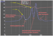
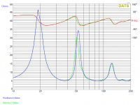
My example involves a completely different multi-resonant alignment though, with much higher tunings .....It was an experiment, but a successful one, and we did end up with quite a lot of useful bass extension below the fundamental tuning although i cannot exactly explain WHY other than an odd minor resonance that became apparent as a tiny dent in the impedance curve at 59hz which (by luck) ended up landing on the lower impedance hump .. The fundamental tuning of the cabinet was verified at 75hz which i was happy to see and the intentional parasitic resonance ended up around the 130hz-ish range (the latter two were both easy to spot in the DATS impedance curve) .........
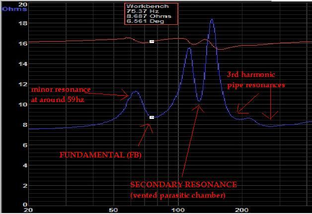
and here again (below) in this measurement seen as a tiny dip or squiggle between 56hz and 58hz :
:
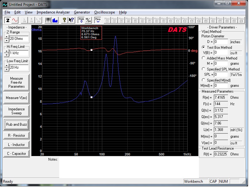
It did not escape me that the frequency at which this odd squiggle was located was very close to the difference between 75hz and 130hz-ish ........ Perhaps some sort of "heterodyning" or "beating" wave behavior effects creating that minor resonance at 59hz? I don't know ... It is still a mystery to me .... I can only guess until i manage to recreate it ...
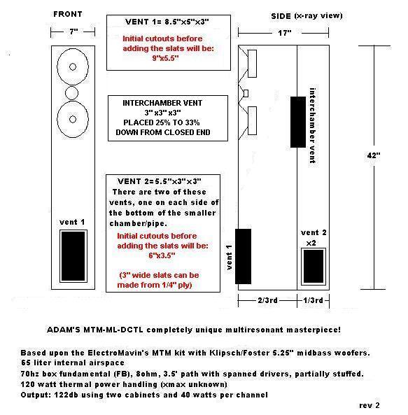
These oddball cabinets were to be the MTM "mains" in my friend's small home theater system .... This was many years ago... These MTM towers were unusual because they were based on a design that was intended to bring together quarterwave resonance accompanied by a parasitic resonance ..... The parasitic resonance was strategically placed near in frequency to the driver's excursion hump with the intent to improve control of the cone movement, similar to the theory behind a DCR( or "ABC") cabinet but with the resonances spaced less than an octave apart.. .... In other words a sort of QWP(TL) + DCR hybrid .... Maybe i could call it a DC-QWP ? ..There was some mass loading in a few places so perhaps MTM-DC-MLQWP ??? hahaha....
The main path was based on a quarterwave resonance and the parasitic resonator was operating on a quasi-halfwave sort of idea that i came up with ......
This was before i learned how to use Akabak and this design was beyond the capabilities of Hornresp so i came up with the theory and sketch based upon some combination of logic and intuition and a lot of luck ....
Here below is the horrible old rough & ugly sketch , and as you can see i wasn't sure what to call it back then either, some parts were out of proportion in this sketch ...
My friend and I built the towers and we set them up on my back patio for a listen, and then in my dining room in order to have further listening tests and some measurements before he took them home .... ....
The towers were rather large for the two small low cost 5.25" woofers (with 118hz Fs ratings) but the result sounded great , HOWEVER their bass extension seemed to be reaching lower than we had expected them to ...... With an Fs rating of around 118hz on the woofers and such a high cabinet tuning i never could have imagined that we would end up with useful response down into the 50s while maintaining control of the cones .....
.....
If i could have known that this was going to be the result i would have tuned the cabinet higher up (as in 33" or 36" height instead of 42")...
ANYWAY, I just thought i might share this strange experience with you guys ............
Johannes, Zero D , Josh, BP1Fan, Just A Guy
Oh and Hello David and Brian! I have something to share which i think pertains to this discussion about some output well below the cabinet's fundamental tuning ....... Even though such a thing would certainly be some rare strangeness, i don't think that it is entirely impossible ...... Not to say that something like this is really going on with the ROAR (i don't know, because i don't own one, and haven't built or measured one so I cannot say from experience) BUT i have observed something in the past which makes me wonder about the possibilities
......................... Can we have a mild or weak resonance down below??? If such a thing is possible could we call it something spooky like "phantom resonance"? I would like that
.. I am not trying to get mixed up in any heated debates about physics or anything like that but maybe you guys will find this interesting ..... I had ranted about this particular project experience over on the Transflex discussion a few times and i would link over to those posts if they were easier to find but that was a while back and those posts are pretty well buried now ..... If i felt like digging for them i would, but i don't, so i will just tell the story again. .
My example involves a completely different multi-resonant alignment though, with much higher tunings .....It was an experiment, but a successful one, and we did end up with quite a lot of useful bass extension below the fundamental tuning although i cannot exactly explain WHY other than an odd minor resonance that became apparent as a tiny dent in the impedance curve at 59hz which (by luck) ended up landing on the lower impedance hump .. The fundamental tuning of the cabinet was verified at 75hz which i was happy to see and the intentional parasitic resonance ended up around the 130hz-ish range (the latter two were both easy to spot in the DATS impedance curve)
.........
and here again (below) in this measurement seen as a tiny dip or squiggle between 56hz and 58hz
:
It did not escape me that the frequency at which this odd squiggle was located was very close to the difference between 75hz and 130hz-ish ........ Perhaps some sort of "heterodyning" or "beating" wave behavior effects creating that minor resonance at 59hz?
I don't know ... It is still a mystery to me .... I can only guess until i manage to recreate it ... These oddball cabinets were to be the MTM "mains" in my friend's small home theater system .... This was many years ago... These MTM towers were unusual because they were based on a design that was intended to bring together quarterwave resonance accompanied by a parasitic resonance ..... The parasitic resonance was strategically placed near in frequency to the driver's excursion hump with the intent to improve control of the cone movement, similar to the theory behind a DCR( or "ABC") cabinet but with the resonances spaced less than an octave apart.. .... In other words a sort of QWP(TL) + DCR hybrid .... Maybe i could call it a DC-QWP ? ..There was some mass loading in a few places so perhaps MTM-DC-MLQWP ???
hahaha.... The main path was based on a quarterwave resonance and the parasitic resonator was operating on a quasi-halfwave sort of idea that i came up with ......
This was before i learned how to use Akabak and this design was beyond the capabilities of Hornresp so i came up with the theory and sketch based upon some combination of logic and intuition and a lot of luck ....
Here below is the horrible old rough & ugly sketch
, and as you can see i wasn't sure what to call it back then either, some parts were out of proportion in this sketch ...
My friend and I built the towers and we set them up on my back patio for a listen, and then in my dining room in order to have further listening tests and some measurements before he took them home .... ....
The towers were rather large for the two small low cost 5.25" woofers (with 118hz Fs ratings) but the result sounded great , HOWEVER their bass extension seemed to be reaching lower than we had expected them to ...... With an Fs rating of around 118hz on the woofers and such a high cabinet tuning i never could have imagined that we would end up with useful response down into the 50s while maintaining control of the cones
..... If i could have known that this was going to be the result i would have tuned the cabinet higher up (as in 33" or 36" height instead of 42")...
ANYWAY, I just thought i might share this strange experience with you guys ....
........
Last edited:
Can there be such things as non linear functions making their presence known as we up the power?
Is there an increased mass loading of the driver with increased power if the design contains let's say roughly 130gram between the driver end the aperture through, and I believe this is important, a constant area?
Please note that these are questions not statements, as I'm unsure about the inertia in compressible fluids (air).
Information for Samuel
Samuel ,
I have a few things worked out for you .. .
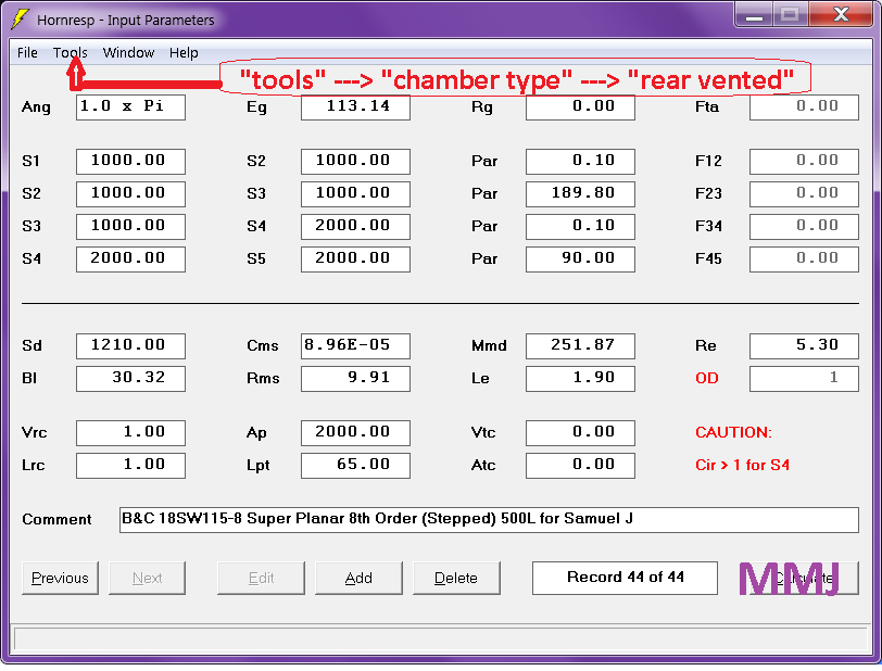
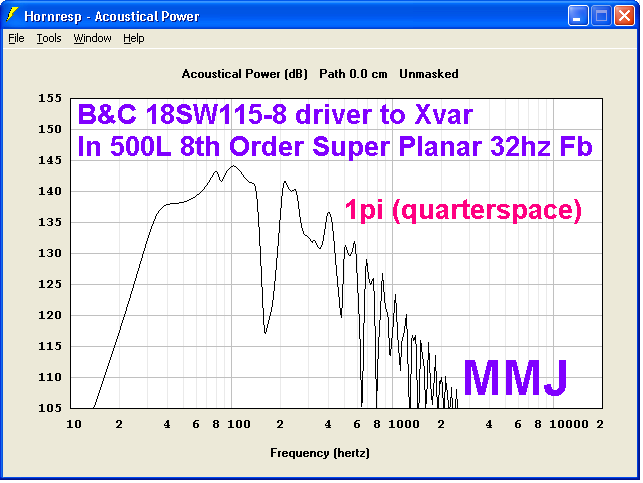
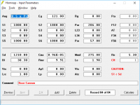
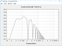
Here are the Hornresp inputs and simulated response chart in 1pi (quarterspace) for an 8th order Super Planar cabinet loaded with a single B&C 18SW115 ... This is with a fundamental tuning of 32hz ... Cabinet volume works out to 500 liters net . .
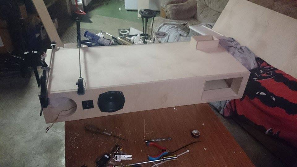
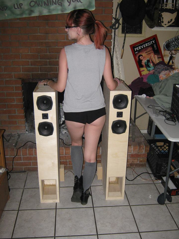
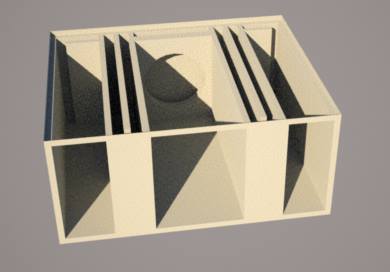
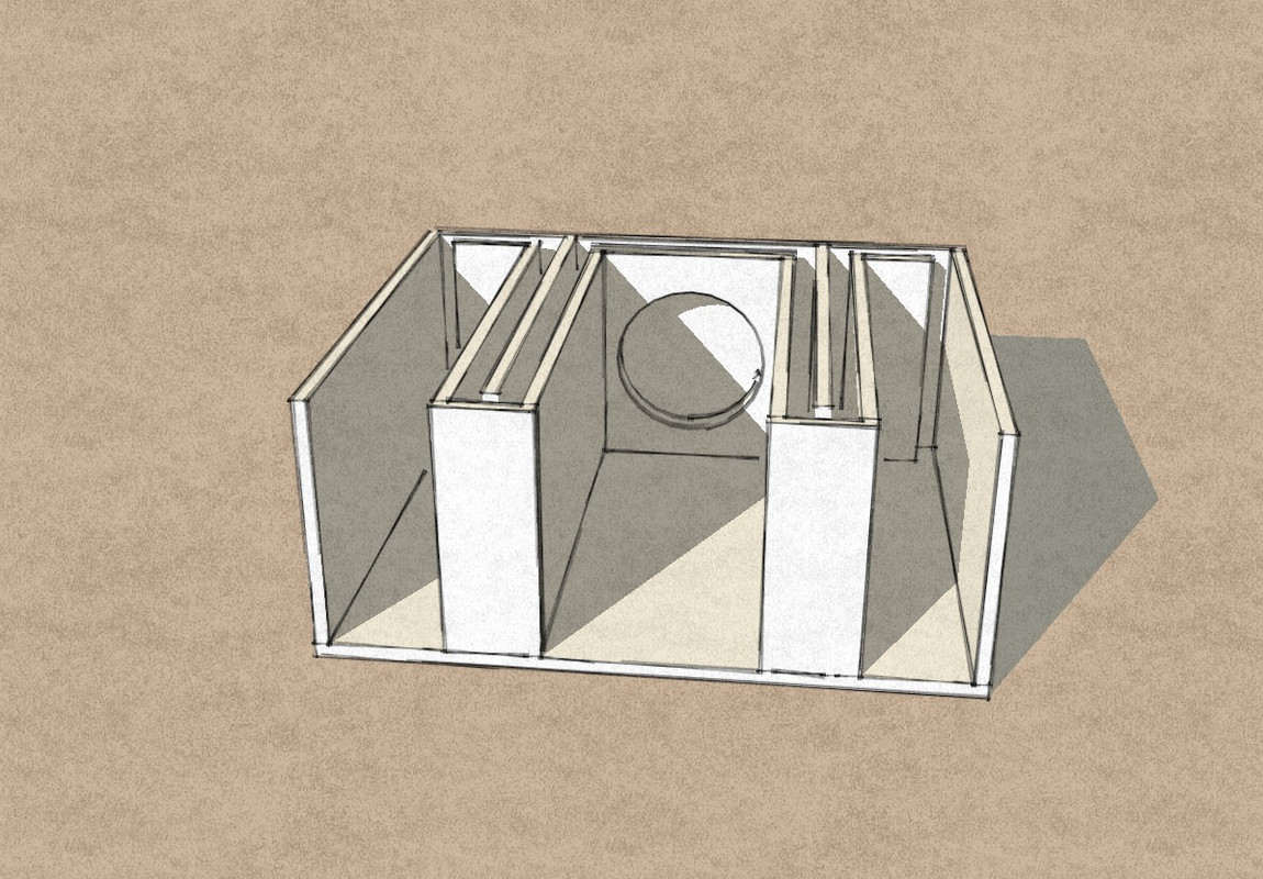
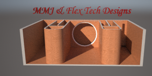
and here (below) are a few examples of the Split-Path Symmetrical style layout ..... You cabinet will look similar to these but not exact ..
I am having my friend Dustin from Flex Tech designs work on the 3d sketch specifically for your cabinet , as well as cut sheet
Samuel ,
I have a few things worked out for you .. .
Here are the Hornresp inputs and simulated response chart in 1pi (quarterspace) for an 8th order Super Planar cabinet loaded with a single B&C 18SW115 ... This is with a fundamental tuning of 32hz ... Cabinet volume works out to 500 liters net . .
and here (below) are a few examples of the Split-Path Symmetrical style layout ..... You cabinet will look similar to these but not exact ..
I am having my friend Dustin from Flex Tech designs work on the 3d sketch specifically for your cabinet , as well as cut sheet
Attachments
@ Matthew Morgan J
Hi, in Post #186 your NOT "horrible old rough & ugly sketch" seems more like a MLTL-DCR hybrid to me.
Ignoring the DCR part for a moment, the f high/low impedances are what we usually see in BR designs etc. So in this case, the f low impedance peak suggests to me that the MLTL part is actually tuned lower than you might have thought ! Unless, it's due to the DCR portion skewing the f high peak, & consequently the f low too ?
Always good to get another chance to see your glamorous assistant again Err, not the bloke LoL
Hi, in Post #186 your NOT "horrible old rough & ugly sketch" seems more like a MLTL-DCR hybrid to me.
Ignoring the DCR part for a moment, the f high/low impedances are what we usually see in BR designs etc. So in this case, the f low impedance peak suggests to me that the MLTL part is actually tuned lower than you might have thought ! Unless, it's due to the DCR portion skewing the f high peak, & consequently the f low too ?
Always good to get another chance to see your glamorous assistant again
Err, not the bloke LoL Attachments
Hi Brian,
It is interesting that for the attached simulation at least, the frequency shift varies from peak to peak. The four tapped horns are connected 2S x 2P rather than 4P, to make it easier to directly compare electrical impedance results. The 2S x 2P shifts shown are the same as those for the 4P case.
Kind regards,
David
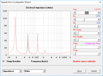
Here's a quick'n'dirty test I did with my POC3.1 TH this morning to demonstrate the impedance shift occurs as expected when the loading on the TH is changed. The blue graph shows the impedance curve of my POC3.1 TH when it's located in the middle of the room (~2PI loading). The light green graph is its impedance curve when located flush up against a wall (~1PI loading). The other image shows the Hornresp sim of the impedance response going from 2PI to 1PI. There is VERY good correlation between sim'd and observed behaviour, particularly when you consider that Hornresp does not sim box losses, so naturally the peaks in the sim are higher than measured in practice.
I suspect that the different observations of what happens when multiple THs are used is dependent on *how* they're being used, because the mouth is so small compared to the cutoff frequency. Stacking two THs side by side so they're both on the ground and their mouths are touching along one side might be the closest one can get to moving from 2PI to 1PI. Putting one on top of the other however may not achieve that goal (one of them is loaded by the ground, the other is not).
(BTW, I might have an idea of how to emulate those box losses in Hornresp, but I need to test the approach a bit more...
)Attachments
An externally hosted image should be here but it was not working when we last tested it.
An externally hosted image should be here but it was not working when we last tested it.
An externally hosted image should be here but it was not working when we last tested it.
That curve looks GREAT for car audio! I could see that enclosure looking awesome in the back of a SUV!


I have not built anything like this but my experience with the ROAR-series is that you should not skimp with the cross section area of the resonators.
You gain almost 2 dB efficiency in the lower part of the passband from increasing the cross section of the resonators (grey line = your simulation - black line = my sim with a larger cross section area).

There is less Group Delay with the larger front resonators and it is much less then the ROAR series.
I really like your compound horn Super Planar quarter wave thingy.... The idea of one of those in a car scares me....
Regards,
Johannes

View attachment 636575
Max spl with 3400 watt and 16 mm Xvar in 0,5 pi radiation angle(car cabin). Add another 10 to 15 dB cabin gain on top of this......
No, you don't get 0.5 pi plus another 10 - 15 db cabin gain. You need to do some actual measurements.
Hi just a guy,
Do you have any thoughts on what might be happening here, in a practical sense? I would very much like to understand what it is about tapped horns that make them perform differently to other low-frequency loudspeakers when configured in multiples. As you know, the classical theory would suggest that the low knee should indeed drop due to the enhanced LF acoustical loading conditions (as can be readily seen in the attached simulation comparing a single tapped horn to four identical units connected in parallel).
Your comments would be appreciated, as always.
It's a real mystery to me...
Kind regards,
David
Hornresp isn't technically wrong, it's just assuming some things that might not be the case in reality.
Part of the issue here is that I tend to make absolute statements when proving or refuting a point so I'll just throw that out there right now ... This is the statement I was refuting.
If you stack several SuperPlanar horns or ROAR18 you gain those few Hz of extension back without the penalty of lower efficiency or large unwieldy boxes.
This statement came from the same post where the author was claiming that removing the high pass filter resulted in a sub so powerful and low that it couldn't even be used because it made everyone sick and despite it's 45 hz tuning it made a great home theater sub. It's heavily implied that the "few hz" you get from stacking THs is "quite a few", based on the context of the post and the amount of absolute bs hype attached to it.
So moving along, let's look at why we don't see much (if any) lowering of the knee when THs are stacked even though Hornresp does predict a bit.
Hornresp assumes that it is simulating a perfectly rigid, axisymmetric horn. It also assumes that a stack of horns is actually one large horn with a round mouth, which in turn assumes perfect coupling of all the elements in the stack. In real life none of this is true and in some cases (depending on how the complete horn is built and stacked) it could be VERY far from the truth.
If you look at the few posts after the one I linked to there are some good answers to why we are seeing this behavior of little or no lowering of the low knee.
Djim suggests that this is what happens IN PARTICULAR when the horns are placed on their sides one atop the other.
Brian suggests that for the Danley measurements it's likely that all 4 horns were stacked before any measurements were taken and then only the appropriate number of horns were powered for the appropriate measurement. That suggests that there was no difference in diffraction (boundary gain) between the 1 vs 4 cab measurements. Even though Hornresp doesn't take diffraction into account it is an important real world phenomenon that likely is not in play in that particular measurement.
This Danley measurement may have been deliberately set up to show the low knee doesn't drop much with stacked, as the Danley tapped horns are marketed as a single cab solution. Regardless of how it was set up though, the low knee wouldn't have dropped much because that's how it usually works in reality.
Weltersys suggests that no enclosure type lowers the low knee much when stacked in real life according to his own measurements. He even shows the Danley measurement that shows the low knee doesn't move much (maybe 1 hz) when a couple of the massive BC218 horns are stacked.
GM suggests that it's all about end correction - which would point to mouth aspect ratio (both stacked and unstacked) vs the round axisymmetric mouth that Hornresp assumes in ALL cases.
These are all valid and pertinent observations and comments about why we don't see much shifting of the low knee when subs of any kind are stacked.
Brian did mention a couple of posts ago that he noticed an impedance shift when a single cab was placed in a corner vs in the middle of the room. This is legitimate and will result in a shift of the low knee by maybe 1 hz. In this case it's not the horn that changes (1 vs multiple stacked horns) it's the boundary that changes so most of Hornresp's assumptions remain valid. There is perfect coupling (there's no way it couldn't be, it's only one horn), the enclosure if very rigid (Brian makes good use of all the tricks to make his cabs rigid, and also a single cab is much more rigid than a stack of cabs), the mouth is about as close to round as you can get with a rectangular cab (so end correction is almost as valid as it could be). So in this particular case most of Hornresp's assumptions are at least mostly true in real life and the low knee does shift - but really not much.
Looking at the 3 measurements I posted, it could be argued that if you took the time to zoom in and mark the actual low knee frequency, all 3 of them dropped by a small amount, an amount so small as to be insignificant.
Now let's look at how much Hornresp predicts the low knee to drop. In the example sim you showed, it looks like the 66 hz low knee shifted down to about 60 hz. That's a difference of about 1/10 octave.
With a more normal 30 hz tuning a 1/10 shift would amount to 3 hz, so that's the maximum theoretical drop that the low knee could shift if everything was perfect (not including diffraction effects).
That's not much, considering that things are seldom perfect and rarely line up with Hornresp's assumptions perfectly in real life because we don't build perfectly rigid round axisymmetric horns that couple perfectly.
Also note that it takes 4 cabs to drop that theoretically perfect 3 hz (based on 30 hz tuning).
This is a far cry from the implications in the post I was replying to.
The ROAR subs are being hyped at an unbelievable level that has no regard for physics. I've noticed a lot of people become seduced with this extraordinary and mostly untrue hype and if these mistakes are not pointed out we'll have half the forum believing that ROAR subs are some kind of magic.
In my post with the measurements I provided a link to the Danley BC 218 thread where all of this was originally brought up. A quick read of that thread will show definitively that the creator of the ROAR and all the hype doesn't really understand how any of this stuff works. He claimed the BC 218 was a tapped horn (it's not), he claimed the 218 had frequency response similar to the what is now know as ROAR subs (it doesn't), he claimed his stepped layout was the only way to get this frequency response (it isn't), he claimed the big dip at the top of the passband was a good thing (it DEFINITELY isn't), and he claimed that the 218 measured lower than expected because turbulent air at the mouth created an extra segment out of thin air. This last is so ridiculous it would be funny, but it's not a joke. He didn't sim the 218 properly (or at all), the measurement was not taken at a high power level so there was no turbulent vortex, and the measurements are completely valid IF you take diffraction (boundary gain) of the massive cab into account.
This type of misinformation is very provocative. For people that don't know better all this hype sounds WONDERFUL. For those that do know better it sound like a load of bull and it's very annoying that it keeps getting posted year after year after evidence of all this has been posted years ago.
View attachment 636575
Max spl with 3400 watt and 16 mm Xvar in 0,5 pi radiation angle(car cabin). Add another 10 to 15 dB cabin gain on top of this......
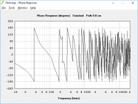
I thought the topology of that "planar horn" looks a lot like a folded up "Bose Cannon", so I did a "Bose Cannon" sim with the same driver and ended up with the attached. Midband SPL is lower, but box size is much smaller (and it should be a lot less complex to build, and more likely to fit in a car). GD through the passband is also much better, and the null is moved above 200 Hz. Xmax in the passband is reached with just under 2.8kW. The phase response through the passband is also much better.
Attachments
Sameul Super Planar Progress Update
Good Afternoon Gentlemen!
This is my first posting ever here, just joined.
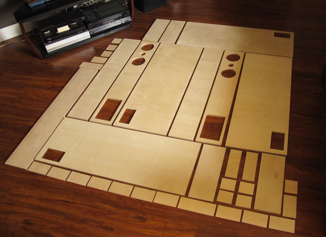
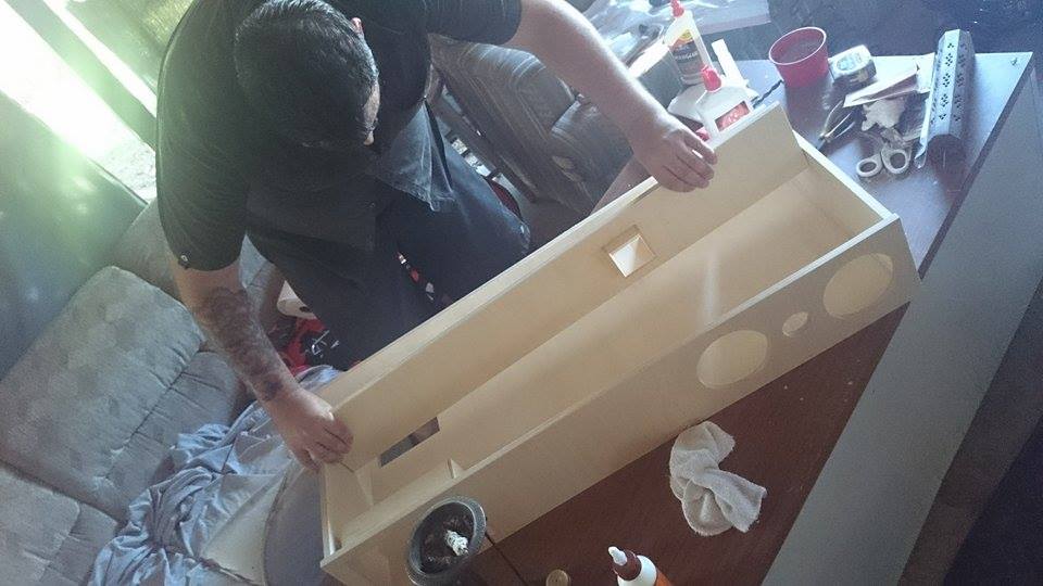
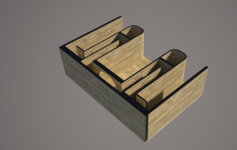
Samuel, I have been working on your Super Planar, Model is complete and now it's moving on to the Cutvisuals parts.
Some Notes On The Building Process-
3/4" Wood is to be used.
-There is some Kerfing present in the front spans of the Mouths/Resonators, as seen in the pictures. MDF is very friendly with kerfing. (If Kerfing is a issue, let me know.)
-Woofer Baffle is Triple-Baffled for structural integrity and panel resonance prevention reasons.
-Shell is Double-Baffled, for panel resonance prevention and structural integrity reasons.
-Folds are Single-Baffled, however there will be appropriate line bracing suggested later in this process.
Thought I Would chime in on progress. Have a good day everyone.
-Dustin Morgan ~ Flex Tech Designs
Good Afternoon Gentlemen!
This is my first posting ever here, just joined.
Samuel, I have been working on your Super Planar, Model is complete and now it's moving on to the Cutvisuals parts.
Some Notes On The Building Process-
3/4" Wood is to be used.
-There is some Kerfing present in the front spans of the Mouths/Resonators, as seen in the pictures. MDF is very friendly with kerfing. (If Kerfing is a issue, let me know.)
-Woofer Baffle is Triple-Baffled for structural integrity and panel resonance prevention reasons.
-Shell is Double-Baffled, for panel resonance prevention and structural integrity reasons.
-Folds are Single-Baffled, however there will be appropriate line bracing suggested later in this process.
Thought I Would chime in on progress. Have a good day everyone.
-Dustin Morgan ~ Flex Tech Designs
Attachments
MMJ, #186 It looks to me like a double tuned back-loaded MTM design.
USRFobi,
Yessir , that's right
- Home
- Loudspeakers
- Subwoofers
- Compound loading 6th order quarterwave "Super Planar" horns and pipes concepts/builds